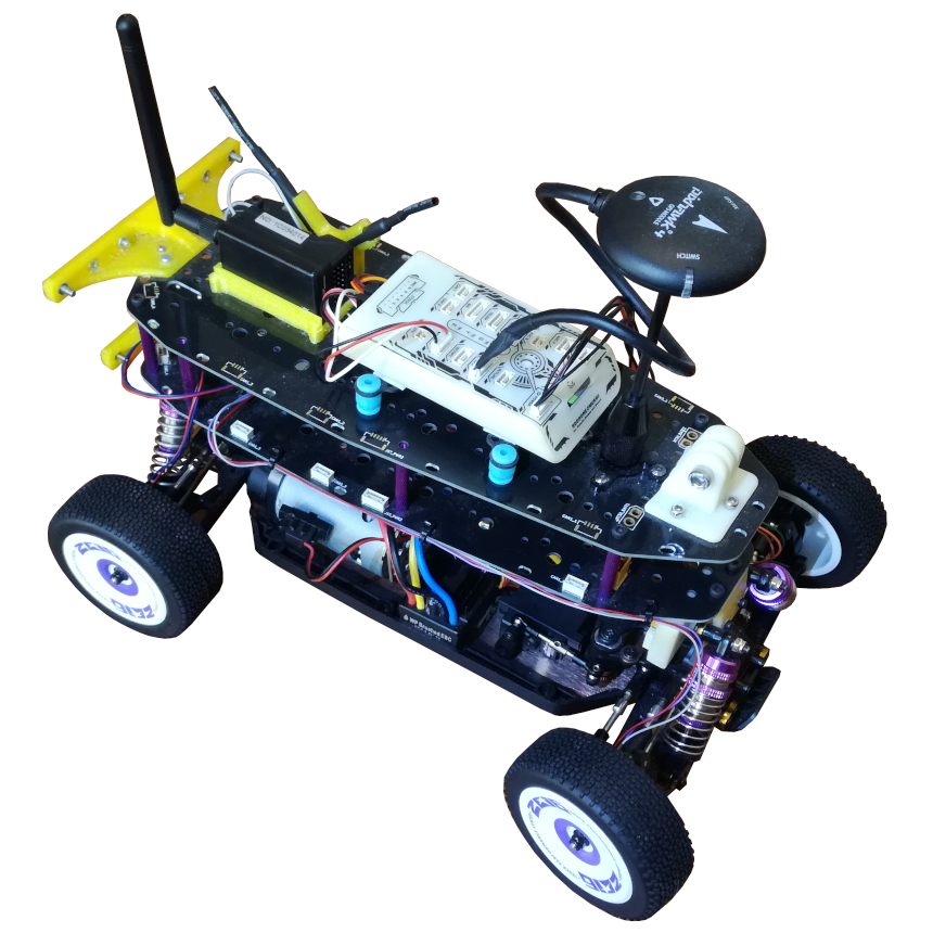
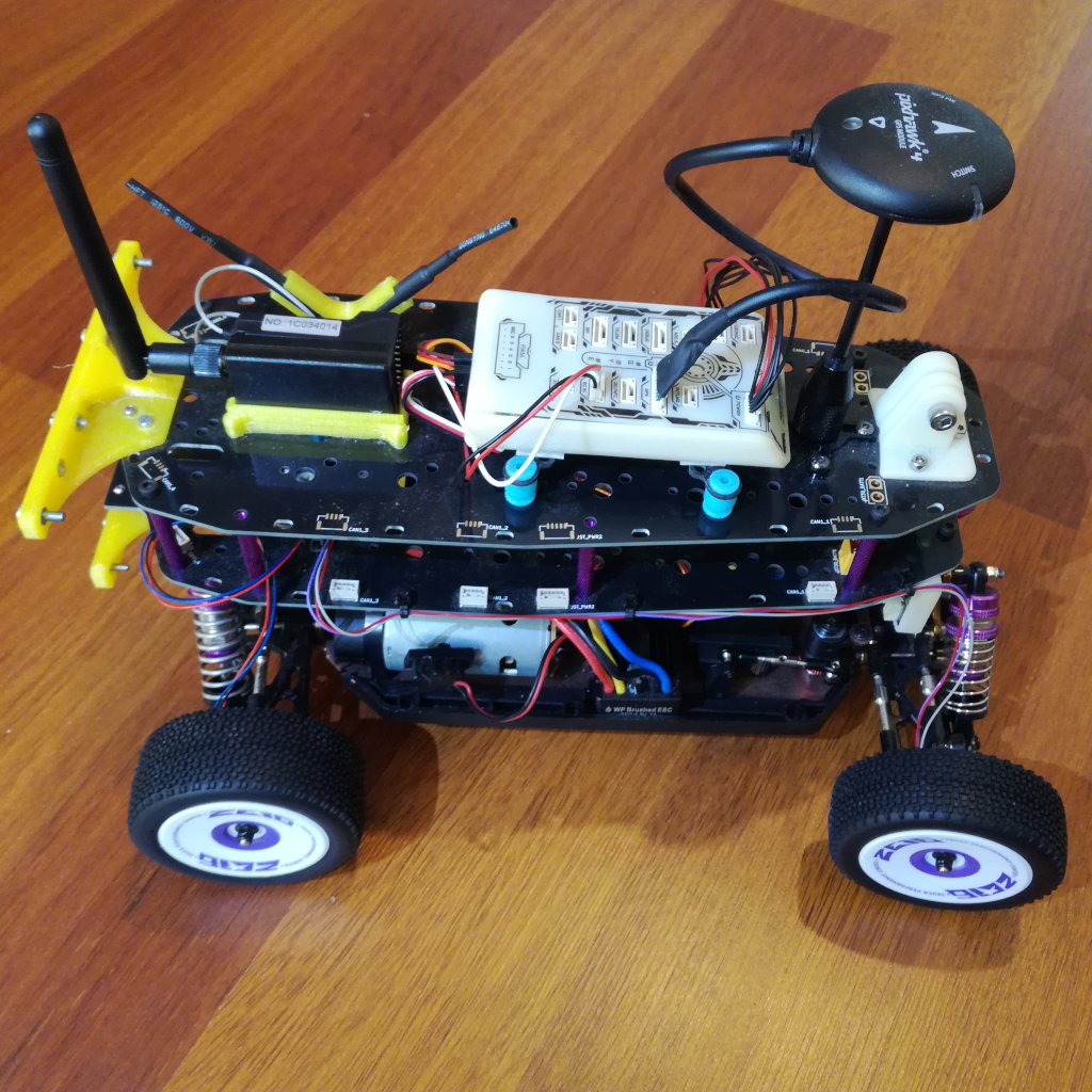
The NXP Mobile Robotics Buggy3 Kit, MR-Buggy3, is a buggy style robotics platform from NXP. It is used for both the NXP HoverGames, for which I acquired mine, and the NXP Cup competitions. The kit includes all the basic hardware to get started with mobile robotics, only missing a 2S LiPo battery:
- RC Buggy: The WL Toys 124019, a 1/12 scale RC buggy chassis.
- Flight/Drive Management Unit: The RDDRONE-FMUK66FMU from NXP, fully compatible with the PX4 Autopilot, and a GPS NEO-M8N module and SEGGER J-Link EDU Mini debugger.
- Replacement Motor ESC and Servo: WP 1080 80A Brushed ESC and JX PDI-1181MG Servo
- RC Remote: The FlySky FS-i6S remote and the FlySky FS-iA6B receiver.
This page will mainly focus on the hardware, and on the buggy itself, providing some insights I found useful and upgrades that I made. For a detailed build guide, and software setup, NXP provides a well written and pictured GitBook.
As mentioned before, the MR-Buggy3 kit contains quite a few parts besides the RC Buggy itself! The figure below shows all the parts that come in this kit, including the provided tools and screw kits:
The basis of the kit is the WL Toys 124019, a 1/12 scale RC Buggy from WL Toys. It has a sibling, the WL Toys 124018, which is a sand buggy. According to this, the WL Toys 124019 is an improved and stretched (45mm longer) version of the WL Toys 144001 which itself is heavily based (cloned) on the LC Racing EMB-1. This means that most replacement and upgrade parts for those cars fit each other! The similarity is clear when looking at pictures from each of them side-by-side:


There are now updated versions of both the WL Toys 124019 and the 124018, the WL Toys 124017 and 124018 respectively (and for the 144001 the 144010). With the biggest upgrade being that the new ones are all brushless.
To transform the WL Toys 124019 RC Buggy into a mobile robotics platform, the MR-Buggy3 kit contains two PCB plates (mid-plates), and mounting hardware for them, that are added on-top of the buggy, providing ample space for sensors and onboard computers. Specifically it has mounting points for the FMUK66 and the NXP NavQPlus companion computer as well as for a camera arm/holder for either the Google Coral Camera or the PixyCam.
I made quite a few upgrades to my MR-Buggy3, some are more important then others:
- New Battery Holder: Battery holder for a larger 2S 5200 mAh LiPo battery.
- New Gearing: Motor pinion changed to reduce speed, required motor mount change as well. The stock gearing is very tall, and not ideal for robotics applications.
Find below the required resources and instructions for each of the upgrades. There are many more that can be done, specially on the WL Toys 124019 chassis. An amazing collection of upgrades with instructions can be found here, which I used as a guide for some of my upgrades.
Battery Holder
The WL Toys 124019 is designed for 2S LiPos, the stock brushed motor is limited by a protection diode soldered to its terminals, and the stock battery holder can fit batteries with sizes of up to 100x10x10 mm. This is a bit small, the recommended LiPo for it has around 3000 mAh to 3800 mAh and are soft shell LiPos. I made the mistake of ordering a larger hardshell LiPo that then did not fit this holder, specifically the OVONIC 2S 50C Hardcase LiPo with 5200 mAh (138x46x24 mm). I decided to figure out a way to fit and secure this LiPo to the Buggy, instead of replacing it with a smaller and less protected/robust one. Two different battery holder designs where considered, one where the battery is mounted horizontally with riser brackets to get the battery above the plastic side skirts of the buggy, as shown in the figure below:
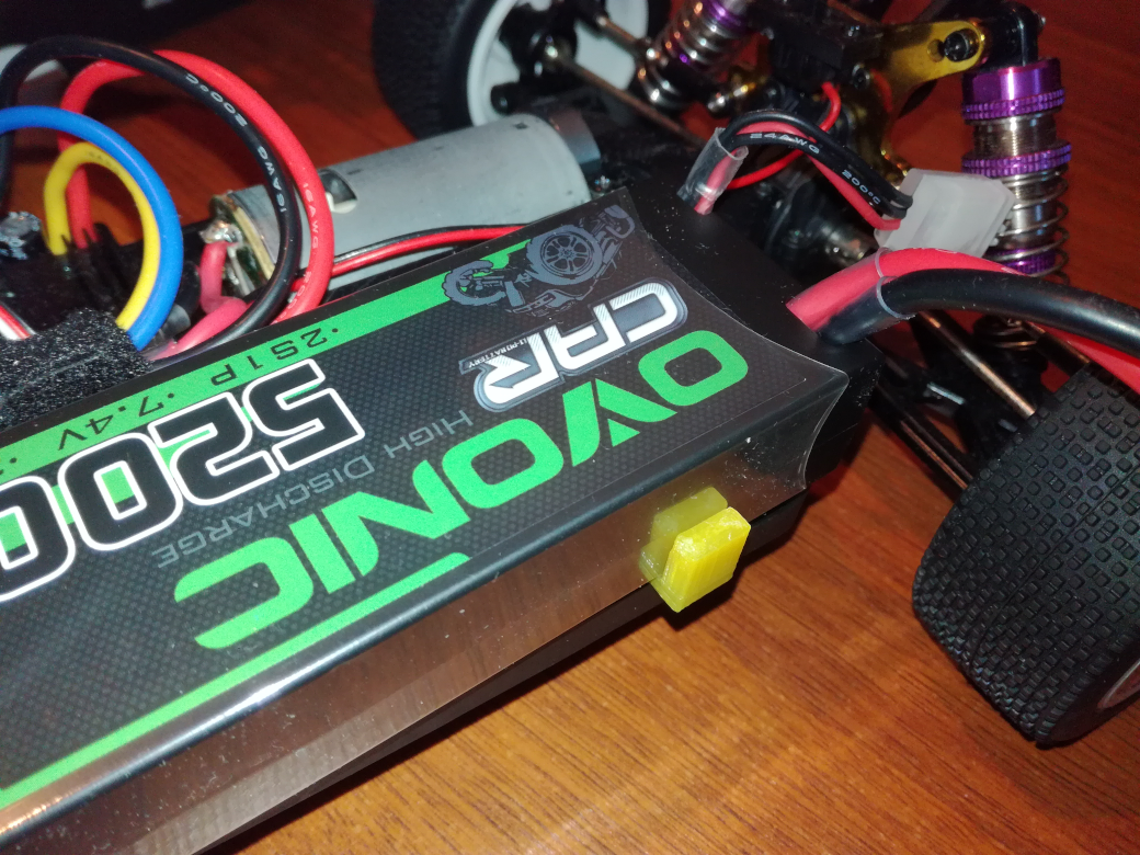
And another where the battery is mounted vertically with a bracket that holds the battery, as shown in the figure below:
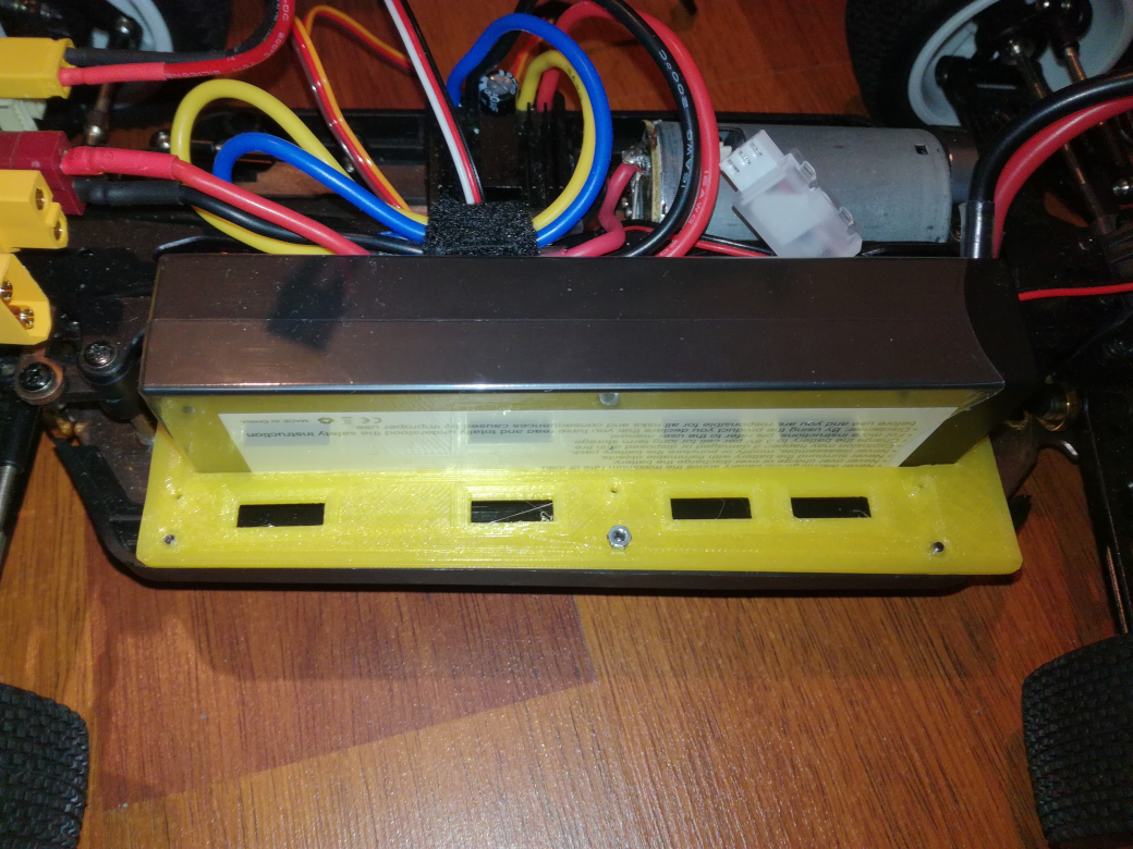
I selected the later one, with the battery mounted vertically, because it keeps the battery better protected and lower, keeping the center of gravity (CG) of the buggy lower and more centered, improving stability. The holder is 3D printed, with the STL file available for download below, and is screwed into place thorough the 3 holes in the side skit of the buggy with 20mm long M2 screws and nuts.
3D File (.stl): Battery_Holder.stl
Motor Mount and Gearing (Brushed)
The stock gearing of the WL Toys 124019 is selected for high top speed, in this case 55 km/h, which is often not the desired configuration for a robotics application where slower driving speed are often required/used. The tall gearing also limits the drive speed control resolution, and the lowest speed possible without stalling the motor. Because of this I took the decision to change the gearing, to a higher ratio (lower speed). I found and followed this guide, which focuses mainly on changing the stock motor with a brushless one (maybe for the future?) but it pointed me into the right direction.
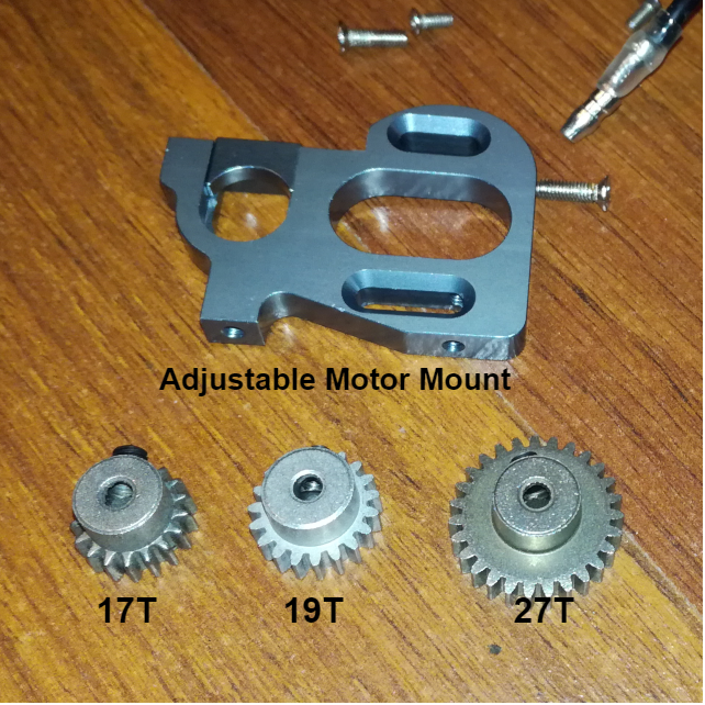
To change the gearing we have to change the pinion gear of the motor, and therefore the motor position has to be adjusted so that the new pinion gear makes contact with the spur gear. This is not possible with the stock motor mount, which is a fixed motor mount with no adjustment possible, and therefore has to be replaced. I ordered a whole kit, that includes an adjustable mount, a 27T (same as the stock) and 19T pinion gears. Additionally I ordered an even smaller pinion gear, a 17T one. The pinion gears need a module 0.7 tooth size and a 3.2mm hole to mount to the motor shaft, not a very common combination. This also means that the pinions from LC Racing (EMB-1) will not fit, they use a different tooth size of module 0.5. The adjustable motor mount from LC Racing can also make problems, but I have not tested it. The acquired parts are shown in the figure below:
With these three pinions (27T, 19T and 17T), and without changing the spur gear (more complicated to do and find), and taking into account the gearing ratio of the differentials of 2.5:1 (12T with 30T gears inside), we get the following gearing ratios and, calculated, top speeds:
| Pinion Gear | Spur Gear | Ratio | Top Speed |
|---|---|---|---|
| 27T (stock) | 44T (stock) | 4.074:1 | 55 km/h |
| 19T | 44T (stock) | 5.789:1 | 39 km/h |
| 17T | 44T (stock) | 6.471:1 | 35 km/h |
I selected the highest gearing ratio and with that an overall gearing ratio reduction of 37%, bring down the top speed from over 55 km/h to a more reasonable 35 km/h, with the added benefit of increased torque. To perform this upgrade, the following steps have to be followed:
Step 1: Remove Mid Plate
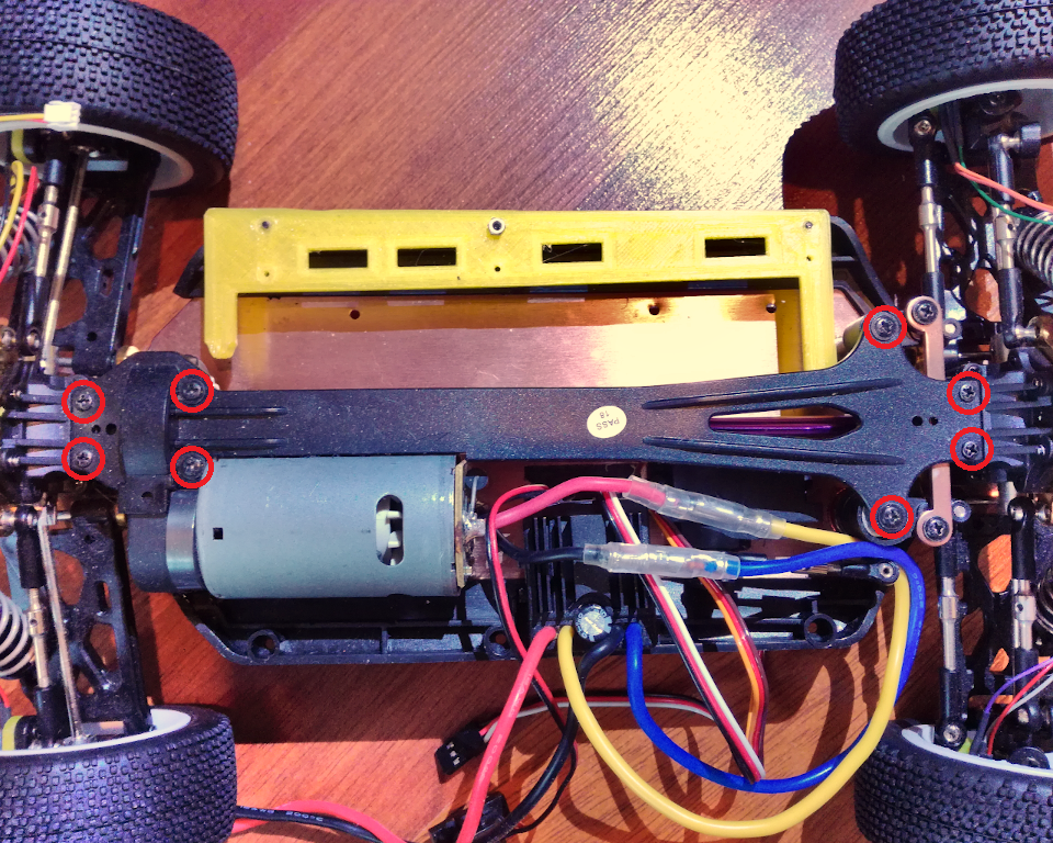
The first step is to remove the buggies mid-plate. It is hold down with 8 screw, 4 towards the back of the buggy, around the spur gear cover, and 4 towards the front of the buggy.
Also remove the gear cover.
Step 2: Unscrew Motor Mount
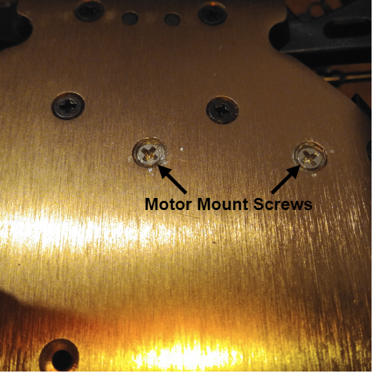
Next, the buggy has to be flipped to get access to the two screws that hold the motor mount to the buggies aluminium chassis. These screws are fixed with loctite and are VERY hard to remove. On the internet I found the advice to heat them up to soften the loctite. I didn't do that and had to trill out the screws, and with that damaged the motor mount.
The motor mount should now fall away, with the motor still attached.
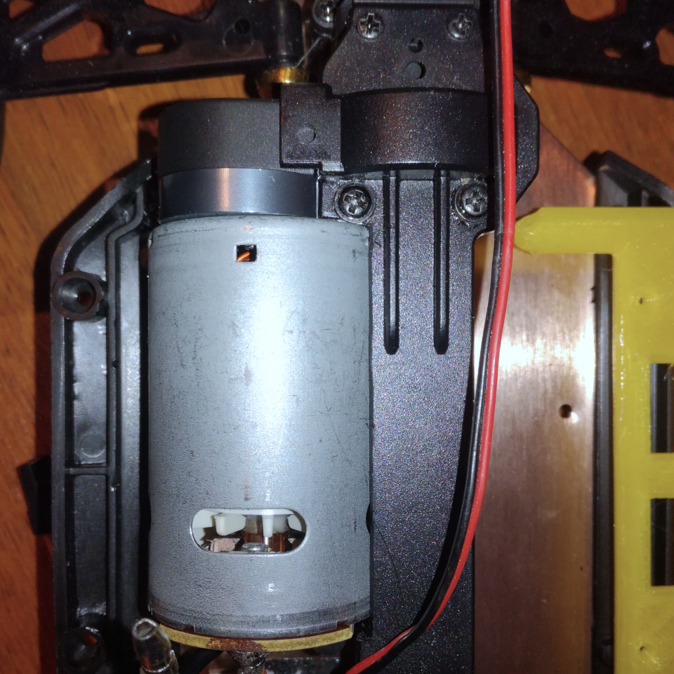
Step 3: Remove Pinion and Motor
With the motor mount assembly removed, the pinion gear can now be removed. Unscrew the two screws inside the pinion gear, again it is fixed with loctite and some heat should help. Again, I didn't do that and had to trill these screws out as well, damaging the pinion and motor shaft.
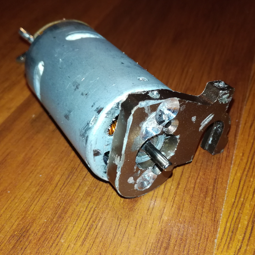
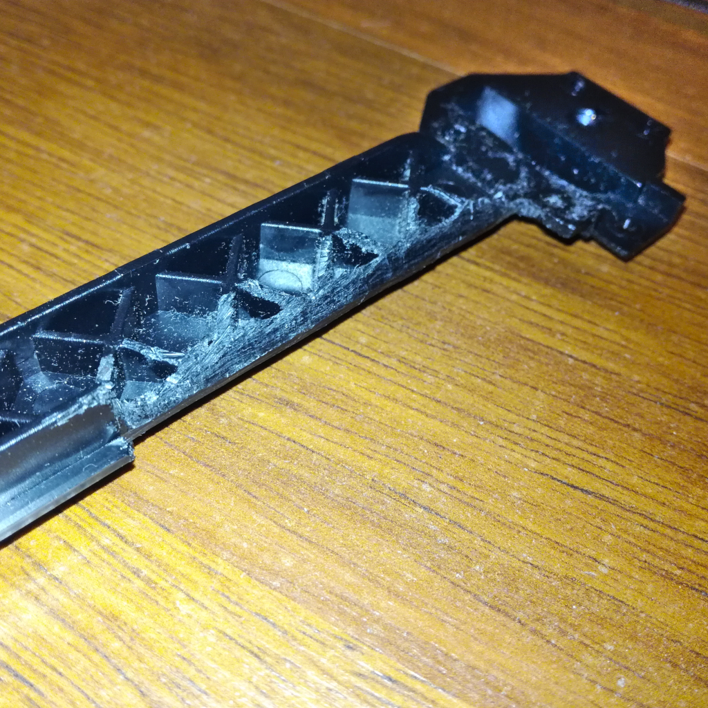
With the pinion removed, the motor can be unscrewed from the mount. And just like all the screws before, these are also fixed with loctite. And again I didn't use heat and drilled the screws out, damaging the motor and requiring a replacement one...
With all the drilling out, and forcing the motor apart from the mount, the final carnage is quite bad as can be seen in this figure, an nothing is recoverable.
Step 4: Add Motor and Pinion
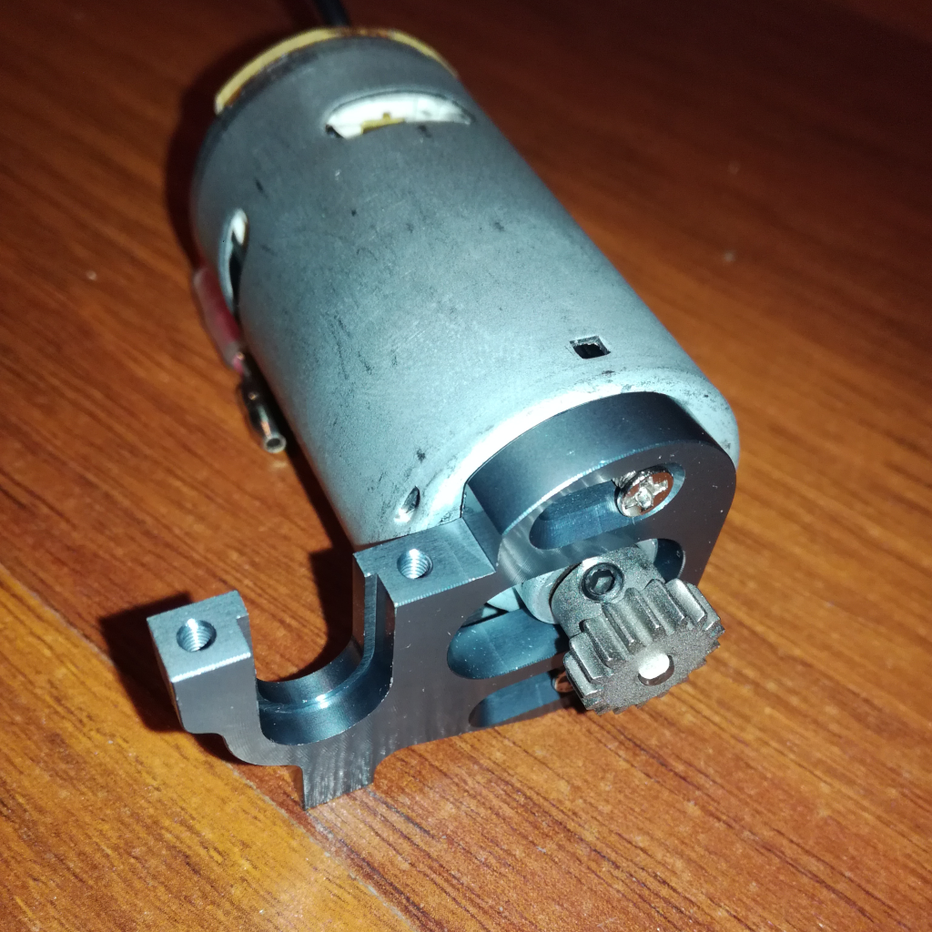
With the pinion removed from the motor and the motor from the motor mount, we can start assembling the new motor mount. First fix the motor to the new adjustable motor mount, don't tighten the screws yet so that the motor position can be adjusted. After that, the new pinion can be screwed to the motor shaft, preferably with some loctite to be safe.
Step 5: Trim Gear Cover
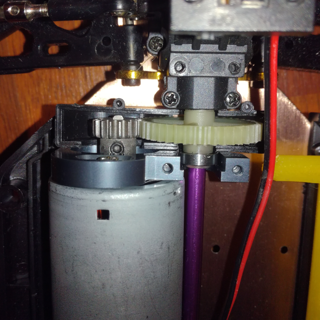
If the new motor assembly is now put in place, and we try to move the motor closer to the drive shaft, to make contact between the pinion and spur gear, we can see that the motor gear cover is in the way... It has to be trimmed to make space to move the motor and pinion closer, just as can be seen in this figure. The plastic is quite soft and can easily be cut with a box-cutter or similar.
Now the motor assembly should fit in place and we can adjust the motor position so that the pinion makes good contact with the spur gear. With this adjusted, the screws from the motor to motor mount can be tightened.
Step 6: Screw Motor Mount
With the motor assembly adjusted, it is time to fix the new motor mount assembly to the buggy aluminium chassis, with two M3x12 (??) countersunk screws. A bit of loctite can be added to avoid loosening of the screws.
The assembly should now look like the one in this figure. Don't forget to slide the small driveshaft bearing holder into the motor mount. I found that the new holders aluminium bearing holder didn't fit well and I ended up reusing the plastic holder of the stock motor mount.
Step 7: Trim Mid-Plate and Gear Cover
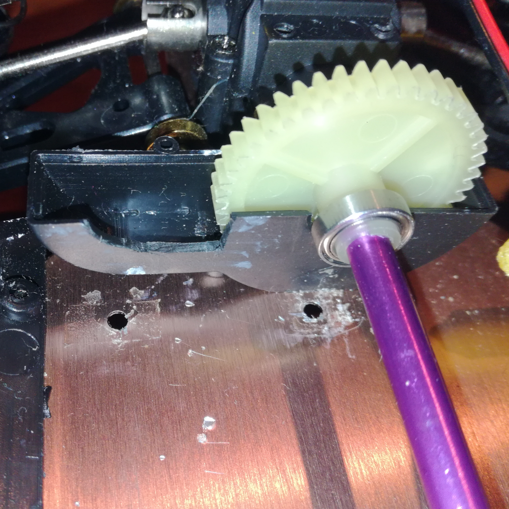
The next step is to add the gear cover and mid-plate back. But first both of them have to be trimmed to accommodate the new motor position. The gear cover is easily adjusted, soft and thin plastic. The mid-plate is a bigger challenge, I recommend using a small handsaw or a rotary tool.
See the figure to get an idea how the final trimmed mid-plate will look like.
Step 8: Add Gear Cover and Mid-Plat
With both the gear cover and mid-plate trimmed, they can now be fixed and screwed in place again. And with that the new motor assembly is complete!
Steering Test
To get the relationship between steering control command, servo control position, and actual steering angle (wheel angle) and with that also the buggies turning radius, the wheel turn angle was measured for different steering commands. The steering commands are given to the FMUK66, which in-turn controls the steering servo. The setup used to measure the steering angle can be seen in the figure below.
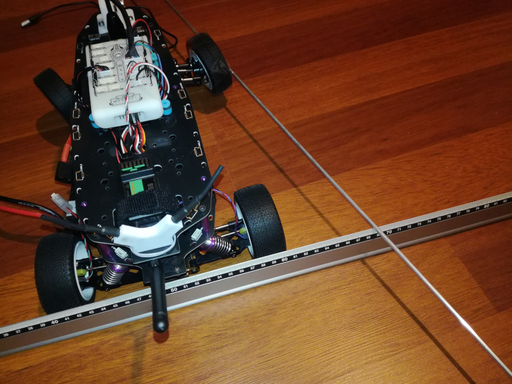
As can be seen, a aluminium rod was tied to the wheel and the distance from resting is measured. With some basic trigonometry, we then can calculate the wheel angle and with that the steering angle as well. The results for this are shown in the figure below, together with the linear trend line.
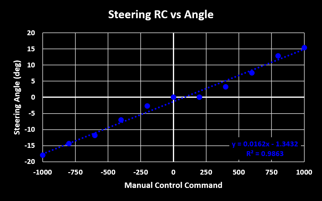
This results are for an out-of-the-box MR-Buggy3, with no changes to the steering hardware or parameters. The linear trend line relationship can now be used for odometry and velocity control, based on the Ackermann steering principles.
Thrust Test
The other useful relationship for odometry and velocity control, as well as just to have an idea, is between the thrust (forward) control command and actual wheel rotation rate, or forward velocity. The wheel velocities are gathered with a developed magnetic Wheel Encoder and with the buggy in the air, free spinning wheels. Using the wheel radius we then can calculate the buggies forward velocity. The results of this test are shown in the figure below:
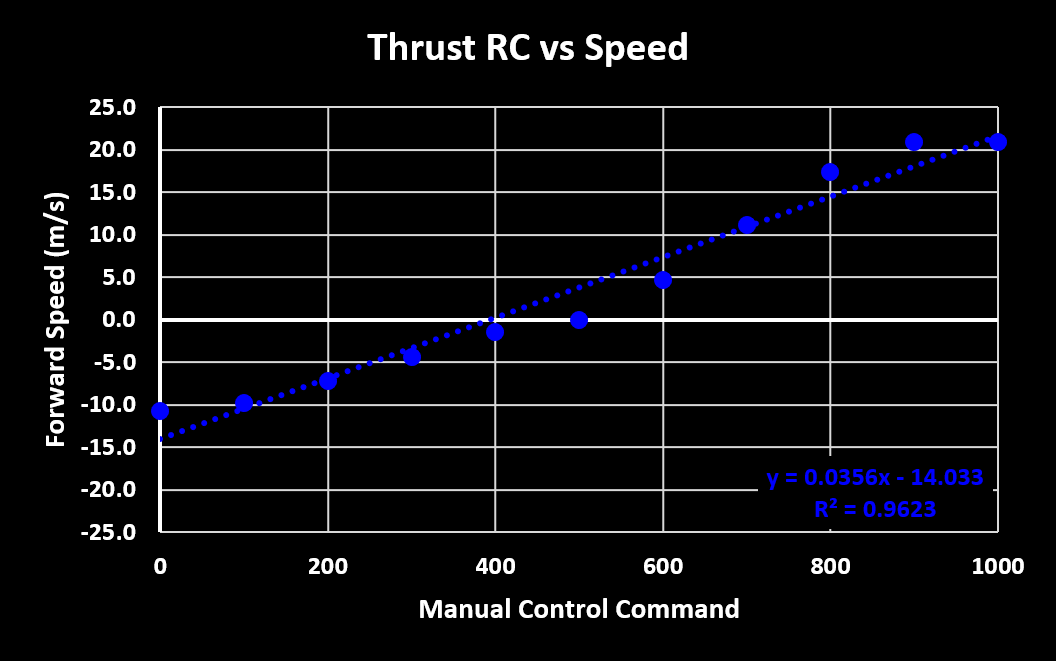
In contrast to the steering results, these results are not withe the out-of-the-box MR-Buggy3 but with the gearing changed as described before. Also, the results are only valid for free spinning wheels and in reality, with the wheels actually moving the buggy, the wheel RPMs and forward velocity will be lower. Real world tests for this still have to be performed. Finally, the used PX4 firmware was V1.14 Beta, which added the ability to drive backwards.