
The idea for this project originated, as with most, many many years ago. There were some previous robot projects but they never got far and often not even out of the dream/planning stage. This project now, the Mini Cube Robot, was started from a clean slate and with the objective to be a base robot that can serve most robotics needs and that will receive many improvements and upgrades over the years. It is designed to be a simple, small and cheap robot that has all the basic features needed and that can be expanded easily. Being small and cheap brings a big advantage for using it in cooperative and swarm robotics where a larger number of robots are used to perform tasks.
The robot platform is a 5x5cm differential drive robot, the dimensions are mostly dictated by the selected motors, two cheap M10 size brushed motors with planetary gears. Besides that, the base sensors are an array of 6 IR reflective sensors (TCRT5000) which give cheap and simple contactless collision sensing with four, two in front and two in the back, backup contact collision sensors. This, together with a motor controller and sensor acquisition board, is what forms the base of the robot, the bare minimum required for almost any wheeled robot. Any additional features can easily be added by stacking additional modules/PCBs on top.
Add-on modules already developed and in development:
- A sensor board for the top with couple (x6) of ToF sensors, forming a cheap low resolution LiDAR with 270° FoV and 5.625° angular resolution.
There are a few modules already planned, with some in early design phase:
- A main control and communication board (probably using a STM32F4 or STM32H7 with bluetooth and NRF24L01+ radios)
- A sensor board with IMU sensors under others
- A dedicated processing board using either a FPGA or a SoC, or a combination of both
Besides the hardware there are many software algorithms to be implemented and tested, under others:
- Integration with PC software, including ROS (python library) and maybe Unity (C# library) with a costume environment
- Localization, and SLAM, with simple sensors, without high resolution LiDAR
- Path planning with different path finding algorithms (A*, RRT, RDT, FM)
- Cooperative and swarm robotics
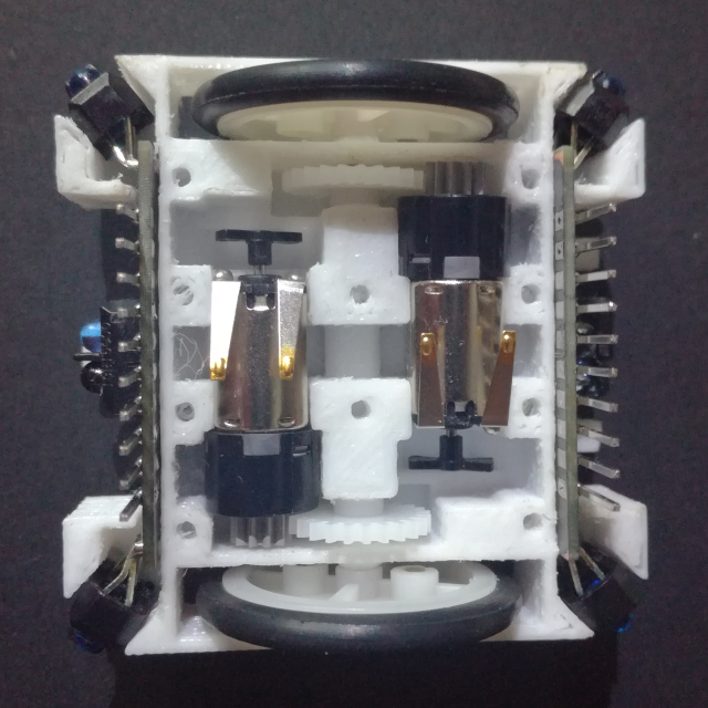
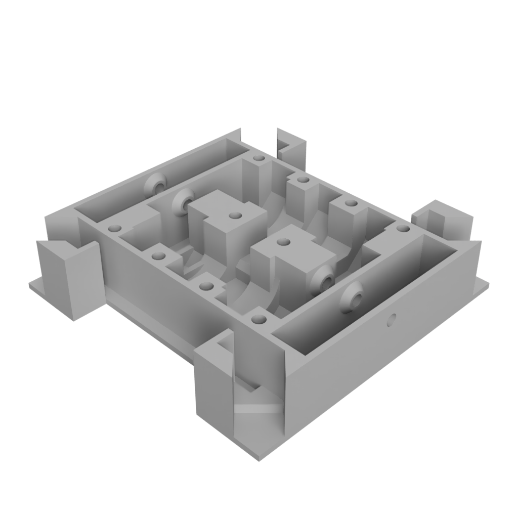
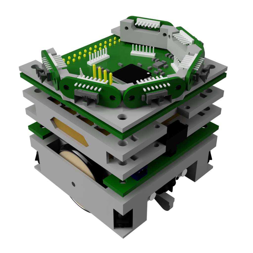
Below is an exploded view of the robot base with all the parts, both mechanical and electrical, visible. The chassis is 3D printed and the mechanical parts are easily found on eBay and/or AliExpress. The 3 PCBs (motor drive, motor encoder, collision sensor) are custom designed to fit snug into the chassis. The current version relies on some special modifications and assembly of both the encoder and collision sensor boards, and they are soldered to the motor drive board. Both is not ideal and will be modified and improved on in future versions.
Assembly
The assembly of the robot base is not complicated but it has a few tricky parts. Below are step by step instructions on how to assemble the robot drivetrain base.
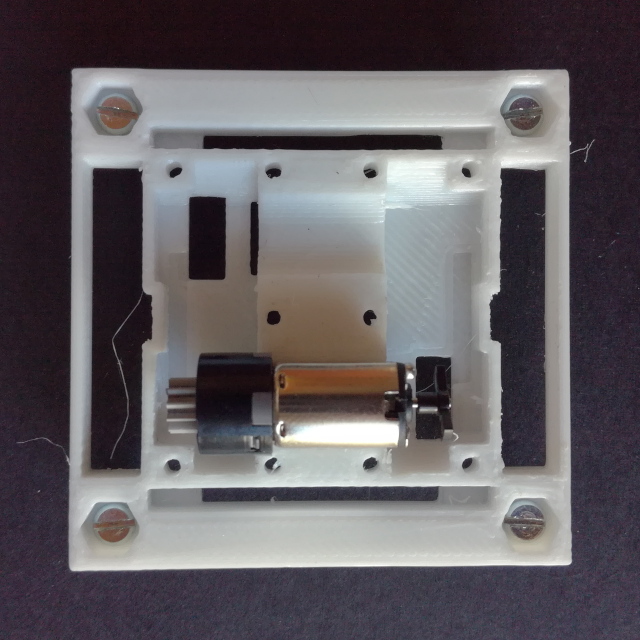
Step 1: Wheels and Gears
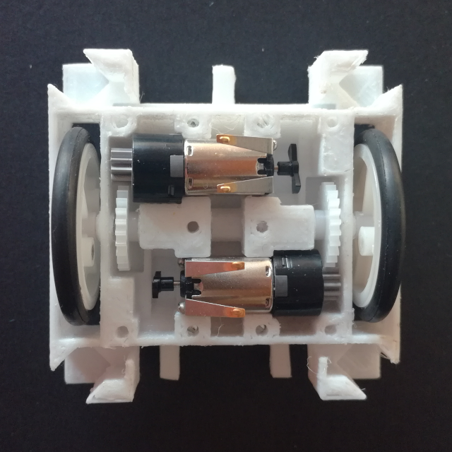
The first part is to add the wheels and gear. Place the wheel into its cutout and start pushing the short metal axels (2mm in diameter and ~18mm long) through the bottom drivetrain holder and the wheel until it starts to pop out on the inside of the drivetrain holder. Add the gear into the slot for it and push the axle further until it is flush with the outside of the drivetrain holder.
The motors can be placed to test the fit and check that the gears make good contact, they will have to be removed again for the top cover assembly.
Step 2: Bottom Skids
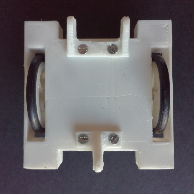
Flip the robot base around to add the bottom skids, this will make the robot stable facilitating further assembly easier. Use two bottom skids, depending on if a down facing reflective senor is used the single and/or double skid, and screw them into the bottom of the drivetrain with 2 M2 countersunk screws. Flip the robot back around.
Step 3: Front Collision Sensor
Next the front and back collision board have to be prepared and slid into place. The IR reflective sensors on either side have to be pent to face 45° away from the board so that it can slide into the bottom drivetrain holder, the fit is very snug. Slide both the back and front facing collision sensor boards in place.
Step 4: Motor Encoders
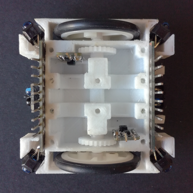
Remove the motors, if they are in there place, to facilitate the gluing of the motor encoder PCBs.
The motor encoder PCBs are glued to a vertical surface located just in front of the opposite drive wheel. The surface has a lip on one side and the bottom which the encoder PCB has to touch/rest on. Use a few drops of super glue, carful to use one compatible with the 3D Printed plastic used.
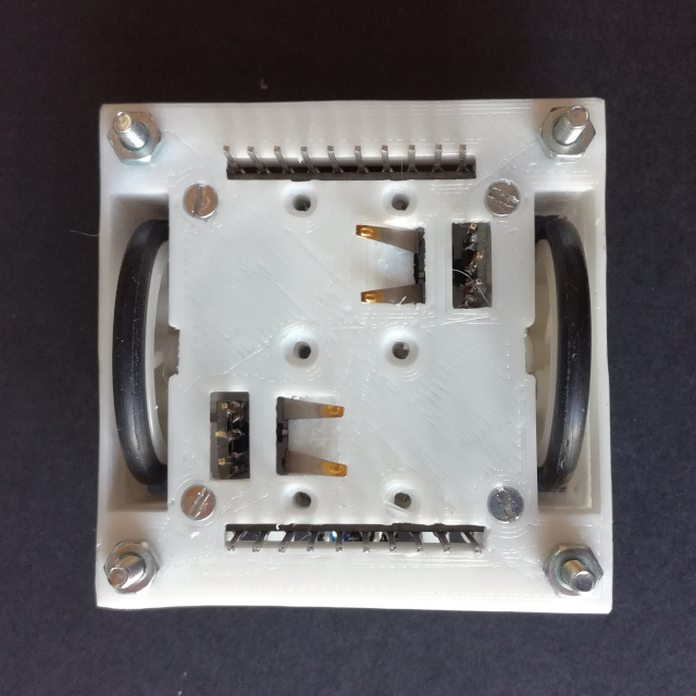
Step 5: Top Cover Preparation
Take the drivetrain top cover and add a M2.5 6mm long screw to each corner, fix the screws in place with a nut on the other side.
To add the drivetrain top cover it is necessary to remove the motors so that the contacts can be slid through there respective holes.
Step 6: Top Cover
Now the whole drivetrain top cover has to be flipped and placed onto the bottom part. Fitting all contacts from both the encoder PCBs and collision sensor PCBs as well as keeping the motor contacts in place is a bit tricky.
The drivetrain top cover is then screwed into the bottom part with 4 M2 countersunk screws.
Step 7: Prepare Coil Base
With the top cover added the motor drive board can be added. All the PCB header contacts have to go through there respective holes in the PCB and the motor contact have to make good contact with the pads on the bottom side of the PCB. The PCB is rested on top of the 4 M2.5 nuts and it is fixed in place with 4 M2.5 5mm long female standoffs (like a long nut) screwed onto the remaining part of the M2.5 screws in each corner.
With the drive PCB fixed in place, the encoder and collision sensor contacts have to be solder to the motor drive PCB.
Step 8: Battery Pack
The final step is to add the battery pack. First connect the battery pack to the drive PCB and then align and rest the battery holder, with the switch and battery on it, on top of the standoffs.
Screw the batter holder onto the standoffs with 4 M2.5 5mm long standoffs and add the other battery holder piece, this one flipped, on top and screw it in place with another 4 M2.5 5mm long standoffs.
Motor Driver Board
Revision 1
Schematic: Motor_Driver_Schematic_V1.pdf
Gerber: Motor_Driver_Gerber_V1.zip
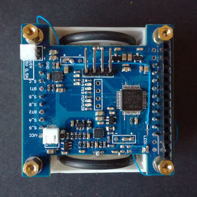
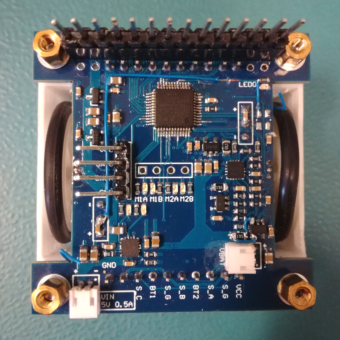
The motor driver board is in the first version. The core of the board is the STM32F103 MCU, which controls the dual H-Bridge motor driver STSPIN240 and acquires the signals from both the collision sensor boards, the motor encoder boards and the signal from two HAL sensors (SS49E) connected on each side of the board next to the wheels, for possible wheel encoding with the use of magnets. The board also has a battery manager IC, to charge and protect a 1S lithium battery. Both the voltage and current from the battery is measured by the MCU as well as the current delivered to each motor.
Below is a view of the motor driver board with the location of all the different blacks/ICs:
As with all Revision 1 Hardware there are some mistakes:
-
One of the encoder outputs is connected to one of the only GPIO pins without interrupt functionality, PD1 which is the oscillator output pin. Although it can be remapped as a GPIO it doesn’t have interrupt support. Also it is remapped together with PD0, the oscillator input, so when using it no external high speed clock source (HSE) can be used. To solve the interrupt problem the LED GPIO is rerouted to the encoder output and vice-versa with two bodge wires, and the external oscillator is not used.
-
The second mistake is with the current monitoring of the battery. The sense resistor is connected the wrong way to the INA180, meaning that instead of measuring the output current the input current is measured. The INA180 doesn’t work in both current flow directions. This was solved with another pair of bodge wires.
-
Another small mistake is that the encoder output is not filtered, and with noise it outputs false pulses/triggers. This was solved with a capacitor connected to the encoder output, to filter out these pulses (as explained in the Results Section).
Below is a figure showing all the bodges on the PCB:
Battery Manager and Power Supply
As the Motor Driver Board is the base board of the robot it is responsible to deliver power for the whole robot. The robot is designed to run on a 1S LiPo battery that is connected to this board. The LiPo battery is connected to a battery manager IC, the BQ24230, that is responsible to both charge the battery as well as to add over discharge protection. The BQ24230 is capable of charing the LiPo with up to 500mA from a 5V supply, and its managed output can deliver up to 500mA of power. The battery is connected to the board through a current sense resistor which allows measuring the current flowing in/out of the battery, the battery voltage is also monitored by the MCU.
The motor driver is connected directly to the batteries and not to the battery manager output so to not use up a significant portion of the available 500mA on that output. This is not a battery over discharge issue because the MCU is powered from the managed output so when the battery manager cuts power the control GPIOs go into idle and disable the motor driver. Everything besides the motor driver is powered from a 3.3V LDO, with up to 250mA, connected to the managed output of the battery manager.
To supply the rest of the robot, like add-on modules and boards, there are 3 different power rails available on the expansion header:
- One rail is connected directly to the battery, it is not managed and has no protection
- One rail is connected to the managed output of the battery manager and therefore has protections but not LDO
- Finally there is a 3.3V rail that is powered from a dedicated LDO, with up to 250mA, that is also connected to the managed output of the battery manager
The two managed rails share the maximum available current of the managed output of 500mA with the driver board.
Motor Driver (H-Bridge)
The two motors are powered and controlled by a dual H-Bridge motor controller, the STSPIN240. It is capable of outputting up to 1.3A and 10V. It has short-circuit and thermal shutdown protection as well as a programmable over-current protection for each motor. The over-current protection is set through a combination of the external current sense resistor value and the over-current reference resistor value (the voltage at the reference pin). Each motor is controlled with a PWM signal to set the motor speed, and a phase input which sets the motor rotation direction.
The motor driver has a dual function enable pin that acts both as an enable and fault detection pin. The MCU pulls the output high to enable the motor driver and if a fault occurs the motor driver pulls the pin low, which is then detected by another MCU pin. The over-current reference pin of the motor driver is also connected to the MCU so that the over-current can programmed with the MCU using a filtered PWM output. Finally, because the motor driver uses external current sense resistors, the motor current is sensed by a current sense amplifier (INA180) connected to these sense resistors.
Expansion Header
The Mini Cube Robot uses a 14-pin 2.56mm header as the backbone connector that is shared by all modules. The backbone connector has 3 power rails supplied by this board, as seen above, and also has pins for three different digital interfaces (UART, SPI and I2C) for communication. Below is the pinout of this backbone connector/header.
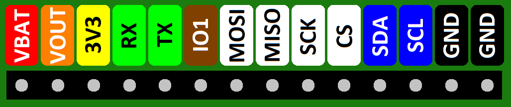
Different modules/boards can have additional headers for more expansions but this header has to be available on all modules and is through which the control communications between different modules/boards is done.
Collision Sensor Board
Revision 1
Schematic: Sensor_Board_Schematic_V1.pdf
Gerber: Sensor_Board_Gerber_V1.zip
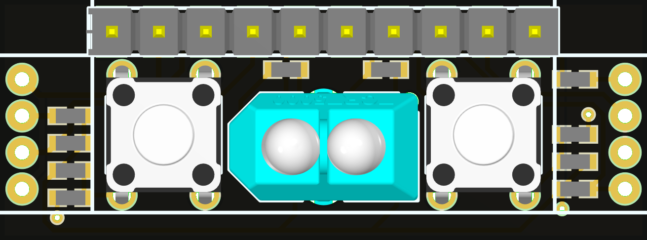
The robot drive base is designed to hold two collision sensor boards, one in the front and one in the back. Each board has three IR reflective collision sensors, the TCRT5000 sensor, and two contact collision sensors (buttons). The three IR reflective sensors are located one at each end of the board and one in the center. The two at each end are mounted vertically and designed to be bent 45° away from the board in a way to cover the largest area around the robot. The center one is mounted horizontally directly to the board so that it faces forward, or it can be bent 90° to face down for surface detection.
Below is a figure showing the collision sensor orientation with the IR LED emitting cone in dark pink and the phototransistor detection cone in light pink. It also shows the robot turn radius in red and the minimum detection distance/circle of an obstacle in orange. This detection circle is the minimum detection distance, of an obstacle at 45° from a sensor which is the worst case, so that the robot stays the turn radius distance away from that obstacle. This means that the IR reflective collision sensors have to be able to detect an obstacle at least 1.5cm away.
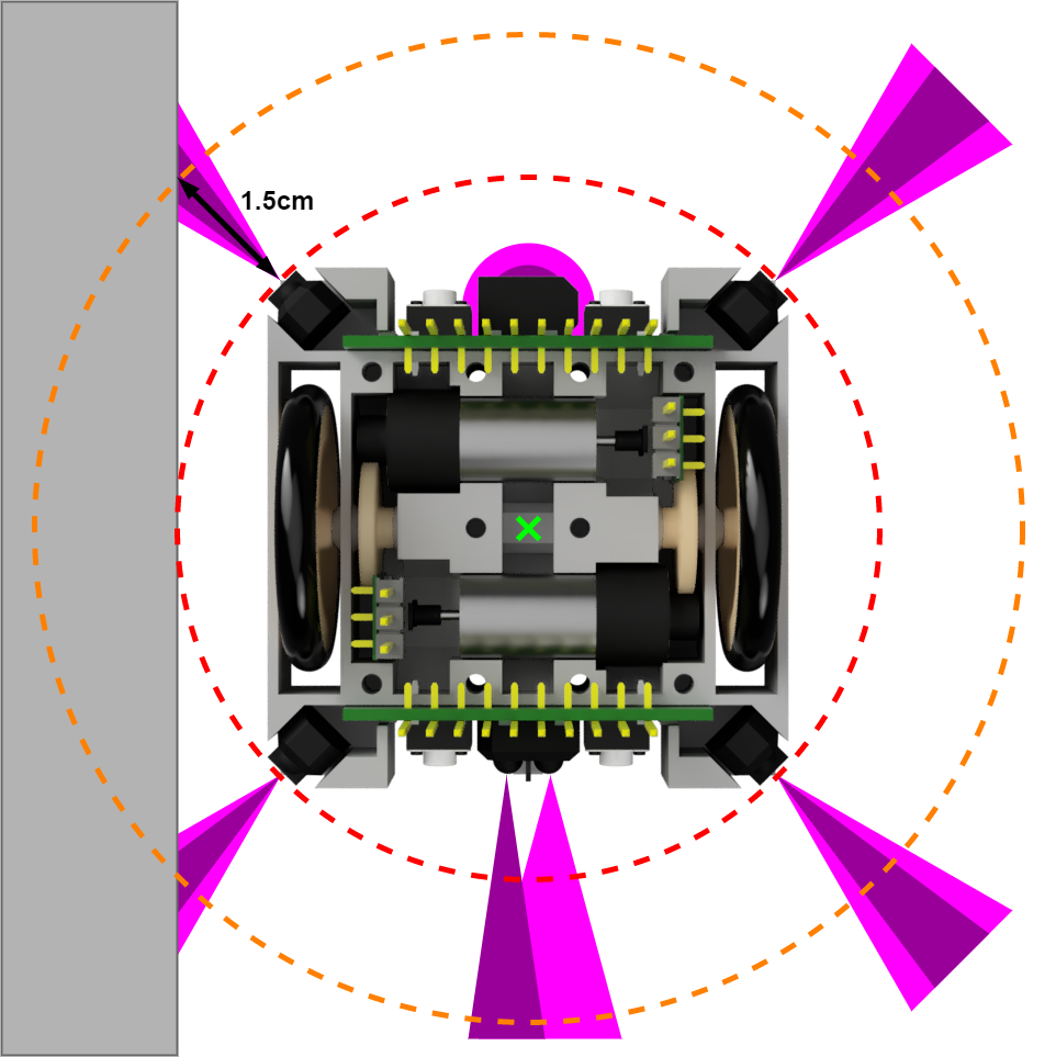
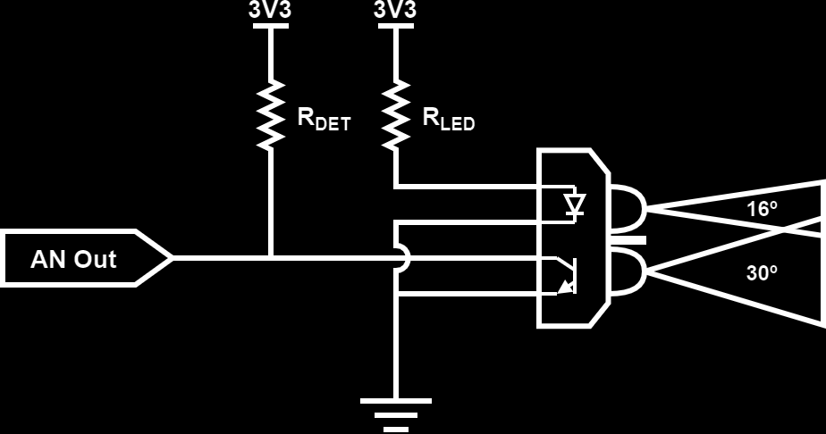
The TCRT5000 IR reflective sensor is composed of a IR emitting diode (LED) and a NPN phototransistor. The IR diode has a emitting angle of around 16° while the receiving NPN phototransistor has a detection angle of around 30°. The IR LED can be powered with up to 100mA, here 20mA are used to safe on power while still providing a good surface detection distance. The phototransistor transforms incoming IR light into current, similar to a solar panel, that can then be transformed into a voltage with the use of a pull-up resistor. The more light the phototransistor receives the lower is the analog output voltage, and because the amount of light received depends on the distance to a reflective target, and the reflectivity of the target, the distance to an obstacle can be estimated. Below is a figure showing the used circuit for the IR collision sensors.
Although each IR reflective sensor LED is powered with a lower current then the maximum recommended, 20mA aka 60mA per board, this is still quite a lot of constant current drain for a small robot. Besides that, the sensors are not read at a very high rate, in part due to using a multiplexed ADC and in part because a high refresh/sampling rate is not required (<= 100Hz). This means that it is useful to be able to turn them off when no reading is in progress, which is most of the time, and safe lot of power. To achieve this, each of the sensors has an independent ground pin on the header so that they can be turned on individually, although the Motor Drive Board connects all GNDs from the same board together and turns each board ON/OFF as a whole due to a lack of GPIO pins available on the MCU.
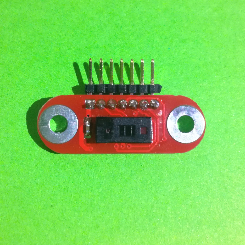
Special attention for assembly
As this is the first version of the robot base, and the PCBs, there are some modifications needed so that the collision sensor board fits in place. First, the connection headers to use are normal straight 2.56mm headers, not the vertically pent ones, and should be soldered flat onto the front of the PCB with the contact flush to the pads aka the plastic piece hanging over the PCB on the top part.
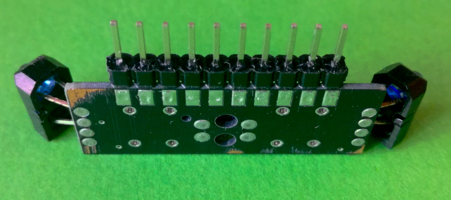
The two side IR reflective sensors have to be soldered with some slack, about 5-7mm (around where there is a small indent in the legs of the LED and the phototransistor), so that they can be bent 45° away from the board.
Finally, the backside of the PCB has to be as flat as possible which requires to file both the legs of the though hole parts and solder contacts on the backside down, as can be seen in the figure below.
Possible improvements and changes for the next version:
- Connecting the phototransistor to the general, not switched, GND so that the ambient IR levels can be measured, without the IR LED turned on
Motor Encoder Board
Revision 1
Schematic: Motor_Encoder_Schematic_V1.pdf
Gerber: Motor_Encoder_Gerber_V1.zip
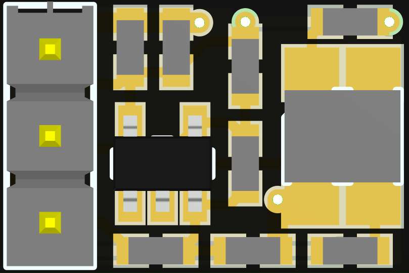
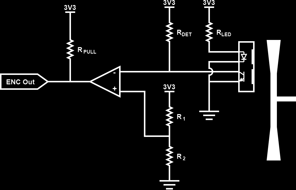
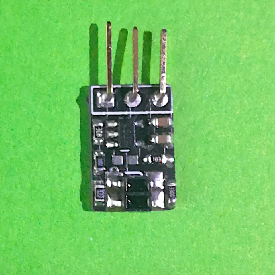
The used motor has a plastic leaf at one end that can be used to measure the robots rotation speed. This is done with the motor encoder board using the ITR8307 IR reflective sensor, composed of a IR emitting diode and a NPN phototransistor, by detect the passing of the leaf. When the leave is over the reflective sensor the IR light is bounced of it and received by the phototransistor generating a small current and therefore a lower voltage at the circuits output, just like with the IR collision sensors.
As here we are not interested in the distance to the reflective surface, encoded in the analog output voltage, but just if the plastic leaf has passed a voltage comparator is added. The analog output voltage is compared with a reference voltage and if it is below the reference voltage the comparator pulls its output low. This way the encoder board outputs a pulse whenever the plastic leaf passes in-front of it, which can be detected by a GPIO Interrupt on the MCU and used to calculate the motor RPM and therefore the robots driving speed. The full electric diagram of the motor encoder can be seen in the figure below:
Special attention for assembly
As with the collision sensor board, some modifications have to be done on the motor encoder PCB as well. Here the used headers are thinner ones then the standard 2.56mm, 2mm headers work well with the plastic part removed and the tip bent 90°. The contacts have to be as flush as possible with the PCB and should not protrude on the backside. The backside can be filed down in case the contacts are to long.
Possible improvements and changes for the next version:
- Exchanging the comparator voltage divider by a potentiometer for easier adjustment, maybe even move the comparator and potentiometer to the Motor Drive Board
Drivetrain Mechanics
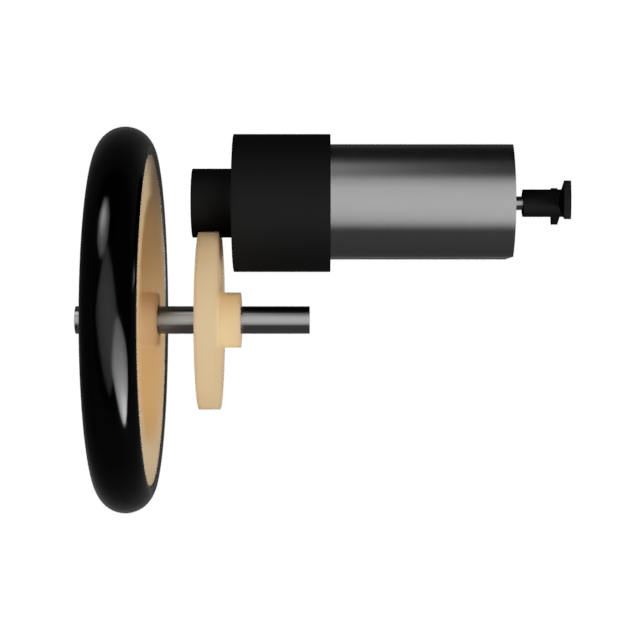
The basis of the drivetrain is the motor, a M10 size motor (8x10x12mm) with a planetary gear (1:171) and a plastic leaf at the other end for an encoder. The motor is rated, according to the seller, for up to 5V with a nominal voltage of 2.5V so it works perfectly in the LiPo battery voltage range between 3.5 and 4.2V. It has a maximum torque, at the planetary gear output of 37.2 mN.m and a maximum RPM of 180 at 5V. There is no information of the maximal power/current draw, only the nominal draw of 40mA. The planetary gear has a 11 tooth Modulus 0.5 gear at its output.
The two wheels are made out of a 242A plastic pulley, 24mm in diameter, with a rubber O-Ring as the tire for better grip. The O-Ring is a 26x3.1mm outer diameter sized one that fits perfectly into the groove of the pulley. This combo can also be bought as complete wheels on eBay or AliExpress. The wheels are mounted to a 2mm diameter and 18mm long steel axel together with a gear that interconnects with the planetary gear output. This drive gear is a 242A (24 tooth) Modulus 0.5 gear, basically the smallest gear that gives sufficient clearance between the drive axel and the motor.
The complete drivetrain gear ratio is then as follows (Motor Planetary Gear + Drive Gear):
$ Ratio = {1 \over 171} * {11 \over 24} = {11 \over 4104} = 0.00268 $
The wheel, pulley with O-Ring, has a combined diameter of ~28.5mm which gives a wheel circumference of ~89.5mm. This means that the robot has a theoretical max speed of 10cm/s, based on the sellers motor specification of 154rpm at 4.2V. The full motor drive speed table can be seen below (based on sellers motor specification and no load):
- 3.0V @ 42mA => 110rpm * 11/24 = 50rpm => 4467 mm/min or 7.4 cm/s
- 3.7V @ 48mA => 135rpm * 11/24 = 62rpm => 5482 mm/min or 9.1 cm/s
- 4.2V @ 52mA => 154rpm * 11/24 = 71rpm => 6254 mm/min or 10.4 cm/s
- 5.0V @ 58mA => 180rpm * 11/24 = 83rpm => 7310 mm/min or 12.2 cm/s
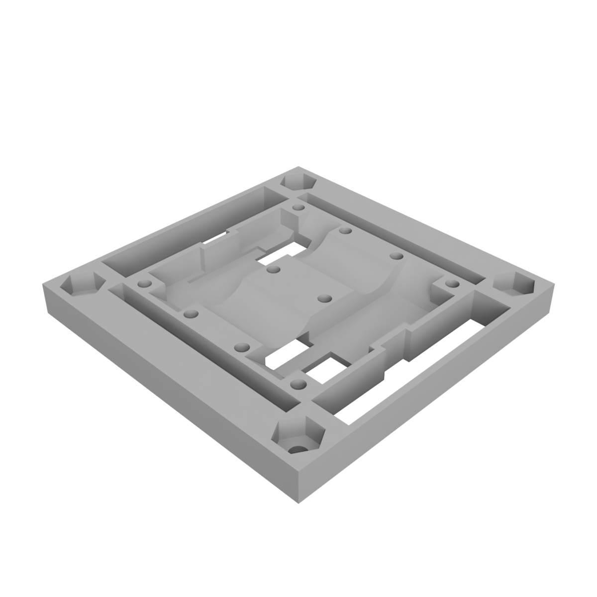
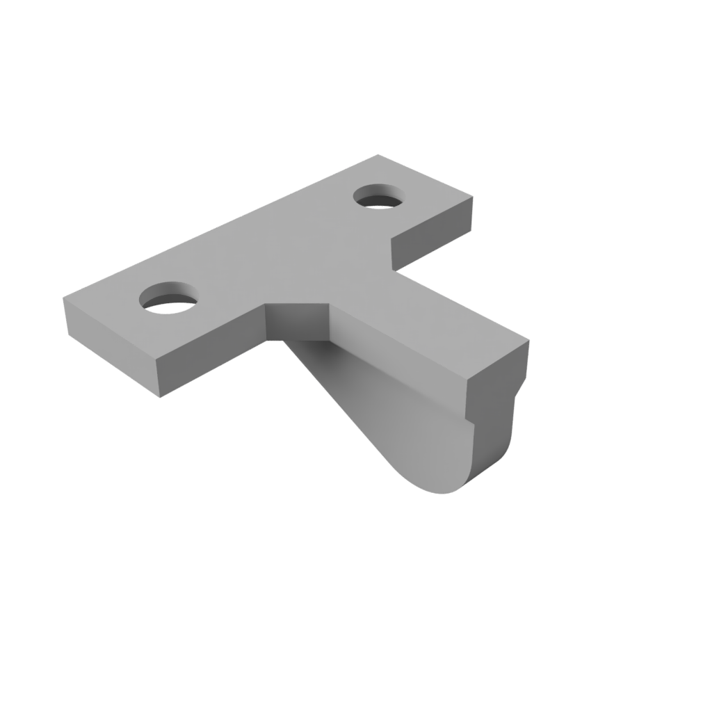
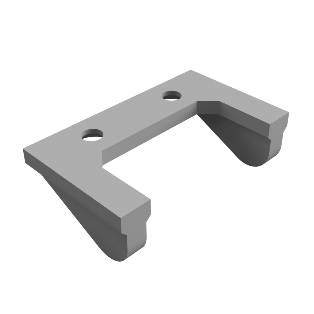
Drivetrain Frame
The robot basis is also the robots drivetrain and is composed of 3(4) different pieces that screw together with countersunk M2 screws. The base piece is the bottom holder, all mechanical parts of the drivetrain are mounted here as well as the motor encoder and collision sensor boards. The encoder boards are glued in place while the collision sensor boards slide into their slits.
To hold it all in place, and to cover the drivetrain mechanics, the top cover is screwed in on top. This piece also has a place to screw in M2.5 screws, or standoffs, in each corner to give mounting posts to both fix the Motor Drive Board to the basis as well as future modules and boards.
At the bottom of the base piece there are holes to screw down skids, either single or double skids depending on if a down facing IR sensor is mounted (it looks down in between the two skids in the double skid version). These skids are needed so that the robot is stable as only two wheels are used. For the best stability both the front and back skid should be mounted so that it can neither tip forward nor backwards.
Below are the .stl files for each of these pieces, ready to be sliced and printed on a 3D printer.
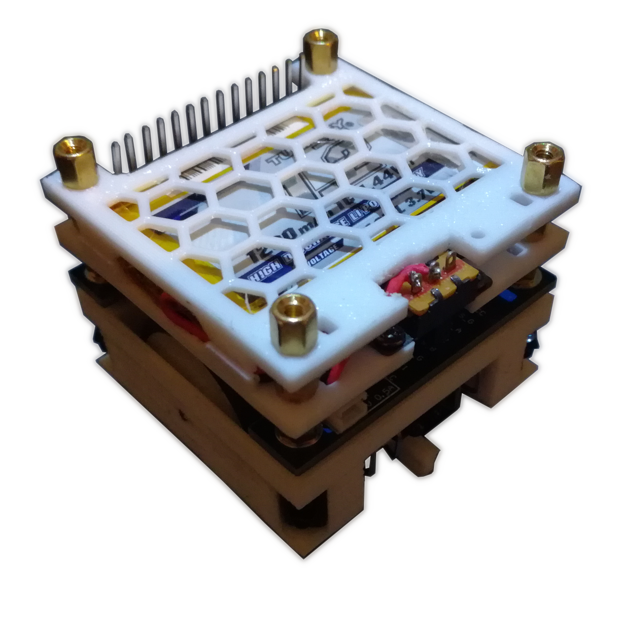
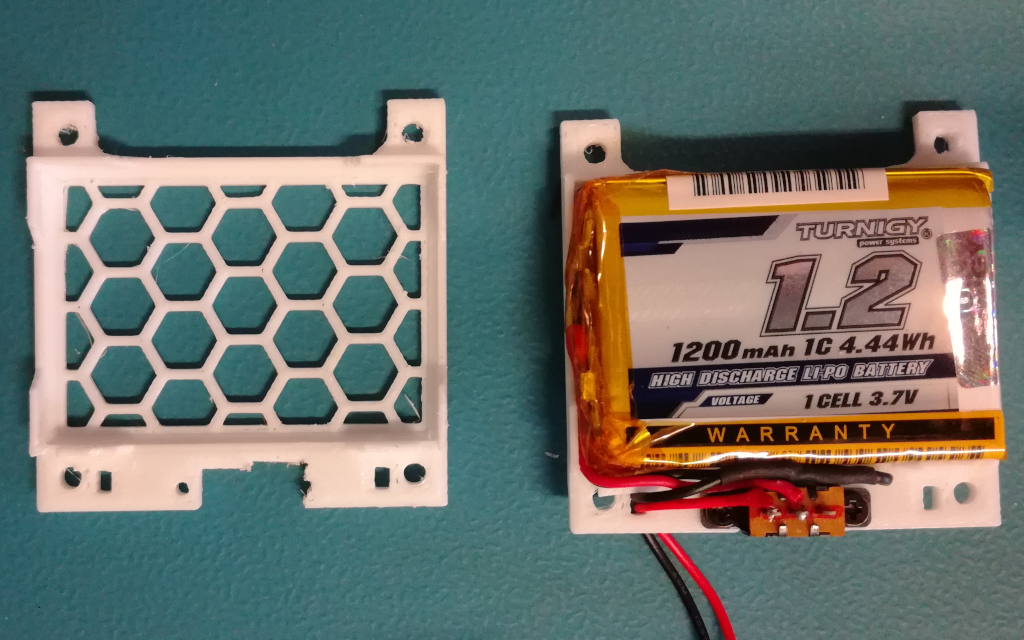
Battery Pack
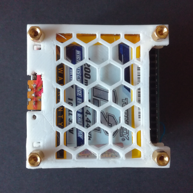
The battery used for the Mini Cube Robot is a 1200 mAh 1S LiPo from Turnigy (HobbyKing). The battery comes with a battery protection circuits but with that the battery is to large and therefore it has to be removed. With it removed the battery is just below 50mm wide so it fits nicely into the robots footprint. The battery is fixed to the robot with a 3D printed holder, which also holds an ON/OFF switch soldered between the battery and the connector to the Motor Drive PCB (2-pin JST-ZH). The figure below shows the assembly of the battery pack, the only pieces missing are the 4 M2.5 standoffs (5mm high) used in-between the two battery pack holders.
Below is the STL file for the battery pack holder parts, two are required with one acting as the base and one as the top:
3D Files (.stl): Battery_Pack_Holder.stl
Interface Protocol
The communication between the different board/modules of the Robot, and with the PC Hub Software, uses a custom messaging system inspired by the ROS messaging system. The developed messaging system is optimized for embedded systems that use low power MCUs (often lack a FPU), avoiding the use of large variables like strings as well as floats whenever possible. This is in contrast to the ROS messaging system with its extensive use of strings and 64-bit floats (doubles). The developed messaging system is called the Micro Robot Message System (uRMS).
Micro Robot Message System (uRMS):
Each message is composed of a small header containing basic information, essentially a stripped down version of the ROS message header, and the actual message information as the payload:
| Byte # | 0 & 1 | 3 -> 6 | 7 & 8 | 9 -> N |
|---|---|---|---|---|
| Meaning: | Topic ID | nsec | Frame ID | Payload |
| Format: | u16 | u32 | u16 | N * u8 |
The Header of each message consists of the Topic ID field, indicating what message is in the payload and equivalent to the Topic ID in ROS but as a u16 instead of a string. It is followed by a timestamp field, the nsec, which is equivalent to the Time field of the ROS Message Header but only carrying the millisecond timestamp as a u32. At the end is the Frame ID, again this is equivalent to the Frame ID field of the ROS Message Header, indicating to which reference frame this message is referred to and in multi-robot system can be used to indicate from/to which robot (which robot frame) the message is. Again, as with the Topic ID field, it is a u16 instead of a string.
The actual message data is carried in the payload area. The messages are, whenever possible, stripped down versions of existing ROS messages, enabling easy conversion from and back the ROS messaging system. Below is a list of all the currently defined and implemented messages, with their respective Topic IDs and content:
The battery message carries the battery system information.
Current: A uint16 holding the battery current consumption in mA
Voltage: A uint16 holding the battery voltage in mV
Charge: A uint16 holding the remaining battery charge in mAh
Percentage: A uint8 holding the battery state of charge in %
Status: A uint8 holding the battery status: 0 for not charging and 1 for charging
The odometry message carries the odometry information of the robot, the velocity and pose of the odometry frame. It is similar to the ROS Odometry Message.
Linear Velocity: A Vector3_q31 holding the linear velocity of the robot odometry frame in Q17.15 m/s
Angular Velocity: A Vector3_q31 holding angular velocity of the robot odometry frame in Q17.15 rad/s
Pose Point: A Vector3_q31 holding position of the robot odometry frame in Q17.15 m
Pose Orientation: A Vector3_q31 holding rotation of the robot odometry frame in Q3.29 rad
The range message carries the distance sensor range information.
Count: A uint8 holding the number of ranging values in the ranges array
Ranges: An array of uint16 holding the ranging information for each distance sensor in mm
The contact message carries the contact/collision sensor information.
Count: A uint8 holding the number of contact/collision values in the contact array
Contact: An array of uint8 holding the contact/collision information for each contact/collision sensor, with 0 as no contact and 1 as contact
The twist message carries a twist motion to be applied to the target frame.
Linear Velocity: A Vector3_q31 holding the linear velocity to be applied to the target frame in Q17.15 m/s
Angular Velocity: A Vector3_q31 holding angular velocity to be applied to the target frame in Q17.15 rad/s
Hardware Level (UART):
The uRMS messages are serialized and can then be transmitted over a wide range of different interfaces, like UART, I2C, SPI, CAN etc… This corresponds to the hardware (physical) layer in the OSI model and is responsible to transmit the uRMS message accurately, error detection is recommended to be added here. For the Mini Cube Robot the base interface used is the UART interface, which is also used to communicate with the PC with a UART Bluetooth Module (HC-05).
The packet format used for the UART interface is shown below. It encompasses the minimum number of fields required to easily transmit data over any point-to-point hardware connection. All field are sent as big-endian (Most Significant Byte first) and MSB (Most Significant Bit first).
| Byte # | 0 & 1 | 2 -> N | N+1 & N+2 |
|---|---|---|---|
| Meaning: | Length | Data | CRC |
| Format: | u16 | N * u8 | u16 |
The first field is the length field (as u16), this field indicates how many bytes are in the data field, this is, the packet length without the length and CRC field. This is necessary for interfaces that don’t have a way to signal the start and end of a packet like the UART. The length field is followed by the data bytes, the serialized uRMS message. The last field is the 16-bit CRC, used to validate the packet. The CRC is calculated over both the length and data field bytes and uses the CRC-CCITT polynomial: $ x^{16} + x^{12} + x^5 + 1 $ (0x1021).
Robot Hub Software
The Robot Hub software is available on Github:
Firmware
The Robot Driver Board firmware is available on Github:
Motor Drive Controller
The Mini Cube Robot motors are driven by a dual H-Bridge, with the motor speed controlled with a PWM signal and the rotation direction with a GPIO. The motor drive controller is responsible to control the PWM signal and the drive direction GPIO according to the desired/set wheel speed. The easiest and most direct controller mechanism to achieve this is with a direct proportional controller, without feedback, where the set wheel speed is directly linked to a PWM value with a experimentally obtained conversion function. Such a simple controller has many problems, for example it has no easy way to handle changes in battery voltage or motor load. This is why a controller with feedback is much better, where the PWM value is adjusted dynamically based on measured wheel speed and this way it corrects for changes in, for example, battery voltage.
The most common controller with feedback is the proportional, integral and derivative (PID) controller. The PID controller takes a error value, the difference between the measured and set value, and calculates the new control output based on it using three different terms, the proportional, integral and derivative term. The figure below shows the general block diagram for a PID controller.
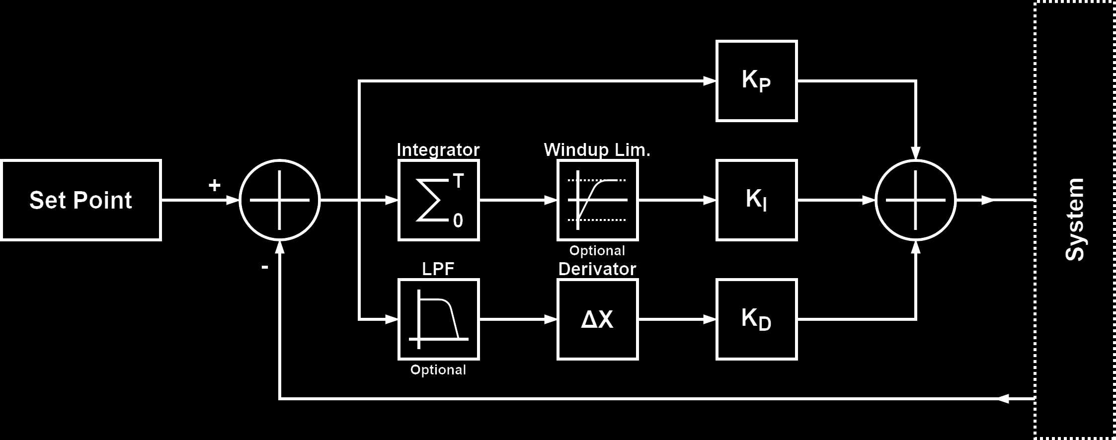
The top arm is the proportional term, where the error value is just multiplied by a constant, the proportional gain (kp). The middle arm is the integral term, here the error value is integrated over time and then multiplied by a constant, the integral gain (ki). The bottom arm is the derivative term, here the error value is derived (difference between previous error and new error) and then multiplied by a constant, the derivative gain (kd). The set of difference equations that implement this are the following:
$$ p[n] = e[n] * kp $$ $$ i[n] = i[n-1] + e[n] * ki $$ $$ d[n] = (e[n-1] - e[n]) * kd $$
The output of the PID controller is simply the sum of all three terms. Depending on the system to control, not all terms are required. Also, to compensate for some problems inherent to the PID controller, additional (optional) signal conditioning blocks can be used. One of these is the windup limiter, which limits the maximum value of the integrator and prevents it to grow indefinitely with residual errors and can also improve system responsiveness. The other often used additional block is a low pass filter in the derivative term, to smoothen the derivative response which is often required in noisy systems to get a stable controller because noise is “amplified” in the derivative term.
For the motor drive controller the set value is the wheel speed, in mm/s, and the controller output is the PWM value. The feedback is provided by the motor encoder, converted to mm/s. The sign of the PID output value determines the motor spin direction and therefore it is used to set the direction pin. In this system, controlling the wheel speed, the output of the PID loop is mainly controlled by the integral term, this because a none zero output (PWM value) is required with a 0 error input, the case for the steady state at a constant speed, and this is only achieved by the integral term. Using the integral term alone would be sufficient but adding the proportional term improves the responsiveness of the system, to changes which take time to propagate thorough the integrator. The derivative term is not required because the system overall is already slow responding, dampened, and additional dampening is therefore not required. For improved performance the PID controller is implemented in fixed point notation.
A good article with some more details on PID controller also intended for use in controlling the movement in a two-wheeled robot can be found here.
Odometry
The odometry system is responsible to track the robots position over time based on the wheel encoder information aka the wheel speeds. Because this is a differential drive robot, the robot is constrained to only two motions: forward translation and rotation around it’s up axis (yaw). The forward translation speed of the robot can be calculated by the following equation:
$$ v_{fw} = { {v_L + v_R} \over 2 } $$
And the rotation speed around the z-axis, yaw, can be calculated by following equation, where Spacing is the distance between the two wheels:
$$ v_{yaw} = { {v_L - v_R} \over {Spacing} } $$
With the wheel speeds in mm/s, the forward translation speed is also given in mm/s while the rotation speed is given in rad/s. The calculated values are in the robot reference frame, centered at the robots center, which moves with the robot and must be converted to a global reference frame, that is stationary. The difference between the two reference frames can be seen in the figure below:
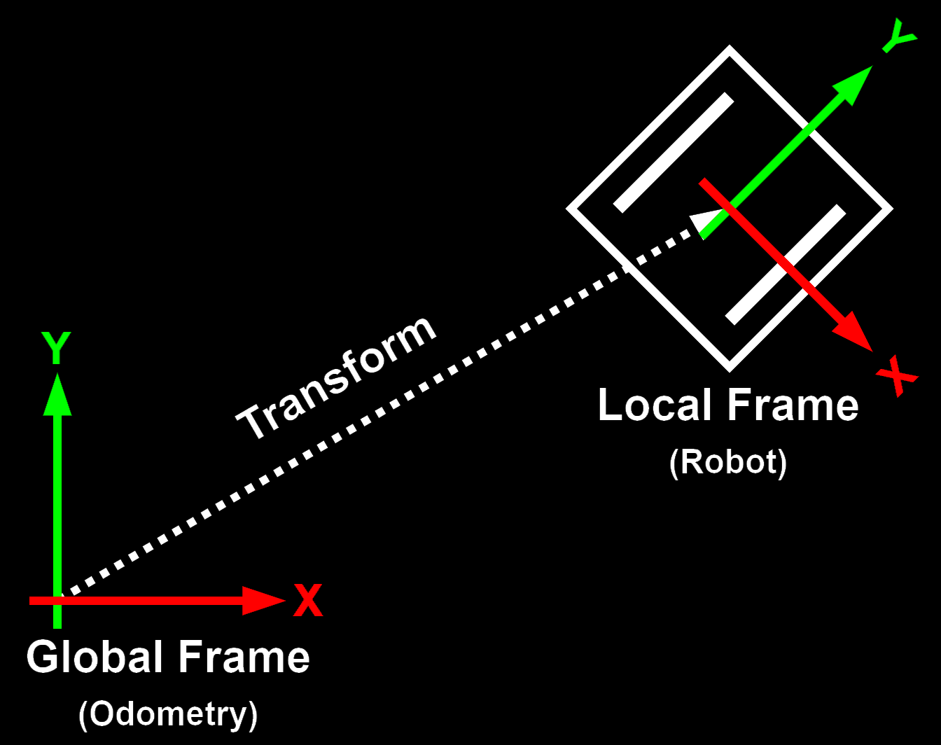
When the two reference frames lay on the same plane, with no tilt (x or y rotation) between them, the up axis (z-axis) of both reference frames are aligned and therefore yaw rotation is the same. The same is not true with the forward translation, which in the global frame will have a component in X and in Y. The conversion is given by the following equations, where the yaw angle is obtained by integrating the yaw rotation speed over time:
$$ v_x = v_{fw} * \cos(yaw) $$ $$ v_y = v_{fw} * \sin(yaw) $$
These now give the robots translation speed in the global frame, and to get the robots position have to be integrated over time.
A great post, from the ROS community forum, about differential drive odometry and the conversion between the two reference frames can be found here.
i.Bus
Uses standard UART with 8-N-1 and 115200 baud.
| Byte # | 0 | 1 | 2 & 3 | 4 & 5 | 6 & 7 | 8 -> 27 | 28 & 29 | 30 & 31 |
|---|---|---|---|---|---|---|---|---|
| Meaning: | Length | Cmd Code | Channel 1 | Channel 2 | Channel 3 | Channel N | Channel 14 | CRC |
| Format: | u8 | u8 | u16 | u16 | u16 | 10x u16 | u16 | u16 |
Motor Encoder
As seen in the Hardware Section, the motor encoder uses a IR reflective sensor with a voltage comparator to convert the analog output to a digital signal. The LED drive resistor, $ R_{LED} $, and the phototransistor resistor, $ R_{DET} $, are tuned to have a low power consumption, dominated by the LED drive current, while still giving a reliable output, a well defined voltage swing when teh plastic leaf passes the sensor. The values used are the following:
$ R_{LED} = 330 \Omega -> ~6mA @ 1.2V $
$ R_{DET} = 47 k\Omega $
With these values a voltage swing of around 250mV with a LED drive current of 6mA is achieved. It is possible to get lower LED drive currents but then the tolerance of both the mounting of the motor encoder PCB as well as the distance to the leaf get low and hard to achieve with the current setup.
The voltage comparator is set to a threshold voltage close to the middle of the output swing. The threshold voltage is set by the $ R_1 $ and $ R_2 $ resistors which form a voltage divider. They are set to a threshold voltage of 2.75V, using the formula below:
$ V_{DET} = VCC {R_2 \over {R_1 + R_2}} = 3.3 {2k \over {2k + 10k}} = 2.75V $
These resistor values give a reliable encoder output, tested and working after glueing the motor encoder in place on more then one chassis. Below are the output signals of the motor encoder, with the output of the phototransistor in green, the threshold voltage in blue and the output of the comparator in red.
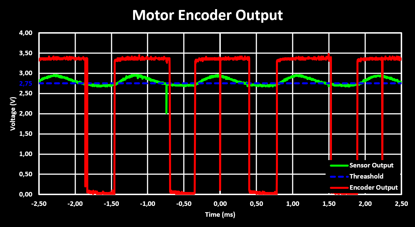
Although the output is reliable, there is a problem with noise on the output voltage of the reflective sensor, which can trigger the voltage comparator and give false output pulses. This can be seen in the figure above as short pulses in the output of the encoder, the red signal. These pulses are captured by the MCU and interpreted as false encoding steps, false passes of the plastic leaf, and therefore result in wrong (higher) RPM values. Although this can be compensated for in digital it is better to handle it in the analog domain already.
There are two methods of solving this in the analog domain. The first and more complex one is adding hysteresis to the voltage comparator, this is the best solution but was not used, at least currently, as the encoders were already glued adn soldered in place when the problem became evident. Therefore the simpler solution is used, to filter the output signal of the motor encoder by adding a capacitor soldered in between the output pin and the supply pin, or the GND pin. The value of the capacitor used is 10nF and the result can be seen in the figure below.
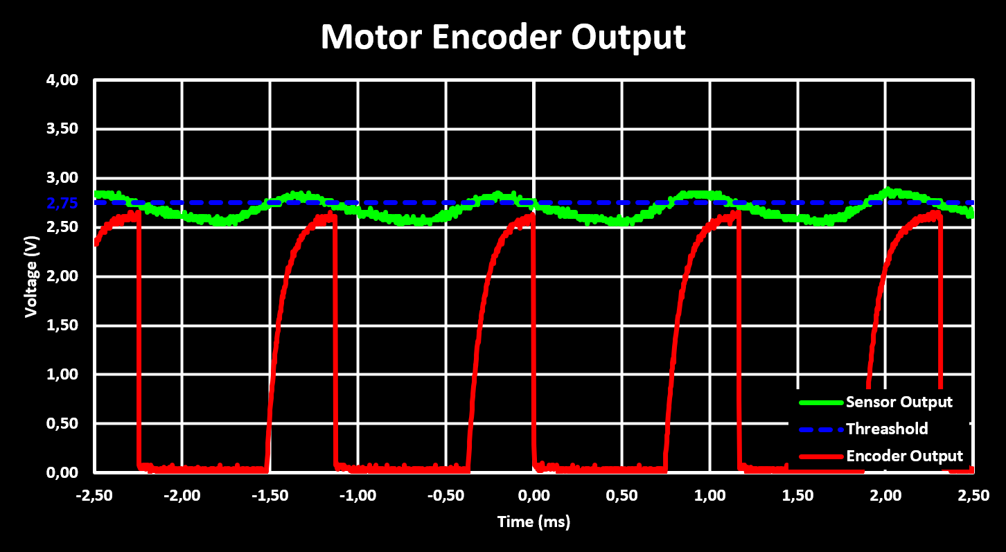
The figure shows that the false pulses are filtered out at the cost of a slower rise time of the output signal and lower high level voltage. The capacitor used was selected to get good filtering while keeping the rise time low enough that at maximum RPM, the figure is taken at maximum RPM, the output reaches a high level voltage above the MCUs high level input voltage threshold, $ V_{IH} $, which is at a worst case $ 0.65 VDD = 2.2V $ according to the datasheet of the STM32F103.
Motor Drive and Speed
As discussed in the hardware section, the motor drive is done with a dual H-Bridge IC, the STSPIN240, and the motor speeds are controlled with a PWM signal. The STSPIN240 is powered directly from the battery and its over-current protection is “disabled” by setting it above the maximum current draw of the motor, set to 500mA. The used PWM frequency in all the test is 1 kHz. Below are figures showing the voltage and current at the motor terminal with three different PWM settings, 25%, 50% and 75%, and with a supply voltage of 4.2V. The current is calculate from the output of the INA180, one connected to each over-current protection sense resistor.
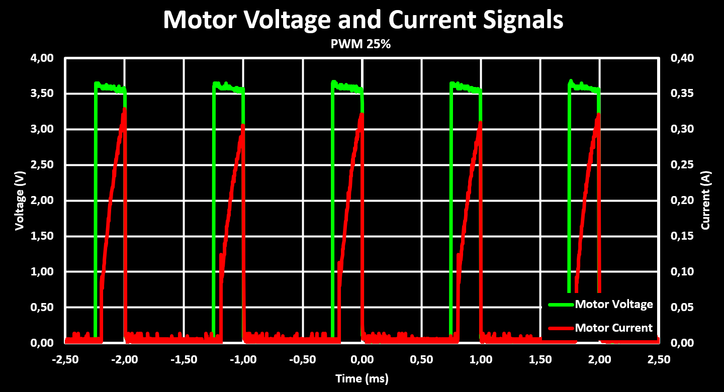
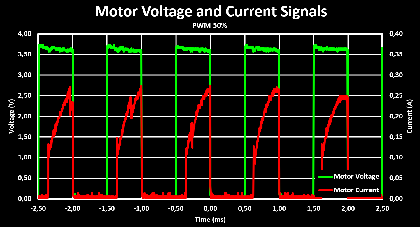
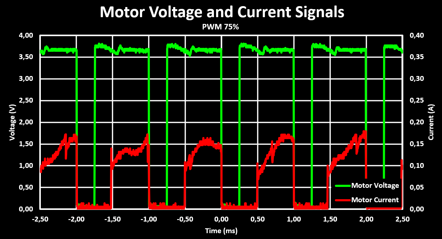
A interesting observation from these figures is that the peak current at the motor is significantly higher with low PWM duty cycles, it increases until reaching 50% and then decreases again. Also, the drive voltage is not perfectly stable, it has some drop that probably can be improved with the addition of larger capacitors but the drop is small enough that it is not a concern. Another observation is that the current draw from the motors has to be sampled at a significantly higher rate, over 10x, then the PWM frequency to get an accurate reading as no analog filter was added to the output of the INA180, an oversight in the design phase, and therefore the filtering has to be done in digital (maybe a capacitor soldered to the output of the INA180 to GND works to).
With both the motor drive and motor encoder working, the RPM of the motors can be measured and plotted for different PWM settings as well as supply voltages. The motor RPM is then converted to wheel RPM, using the gear ratio, and the robot drive speed, using both the gear ratio and wheel circumference. These three plots are shown below.
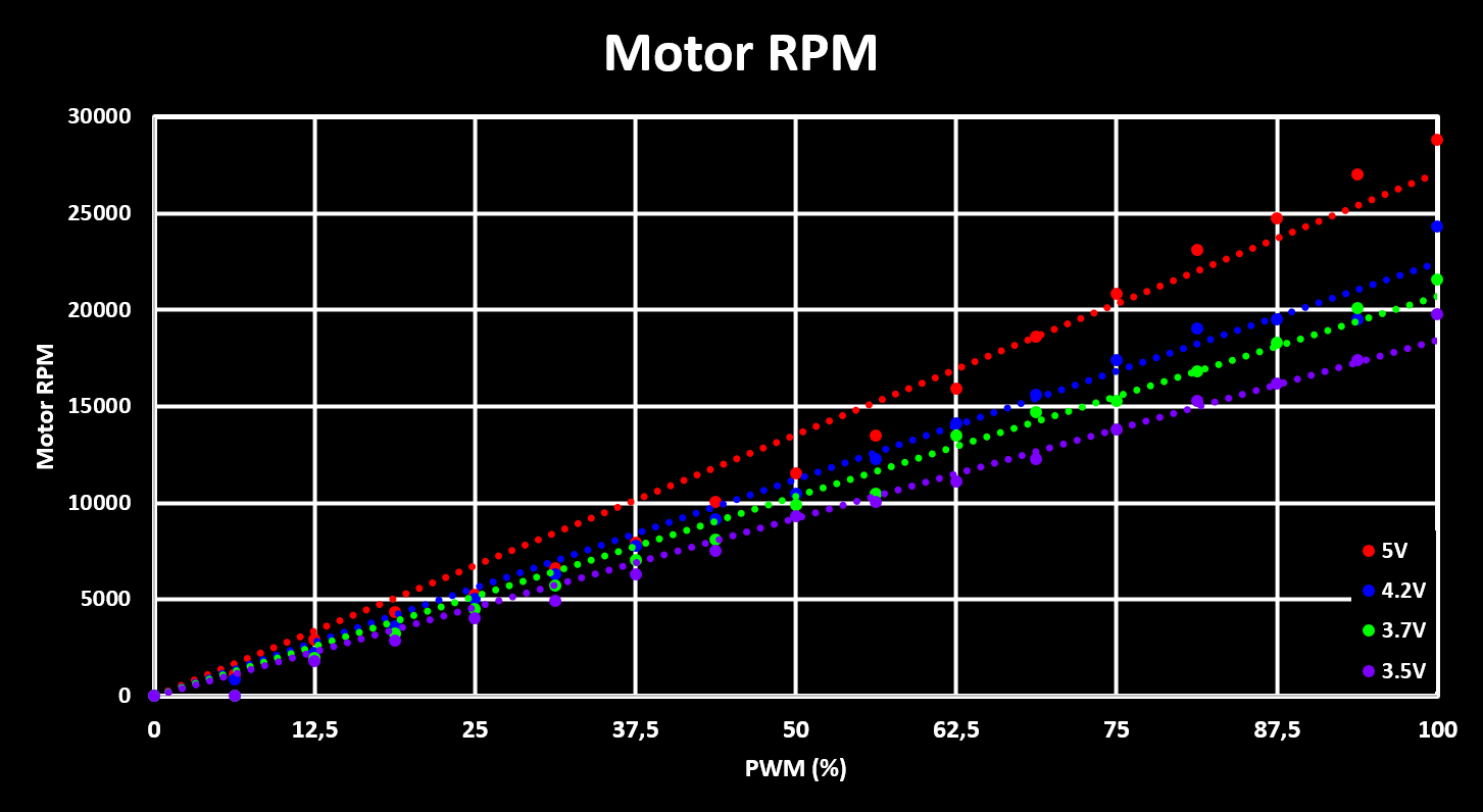
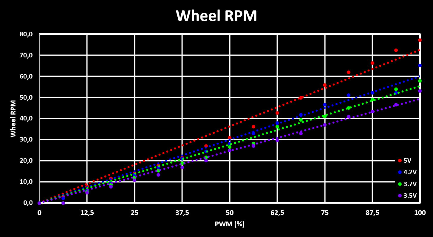
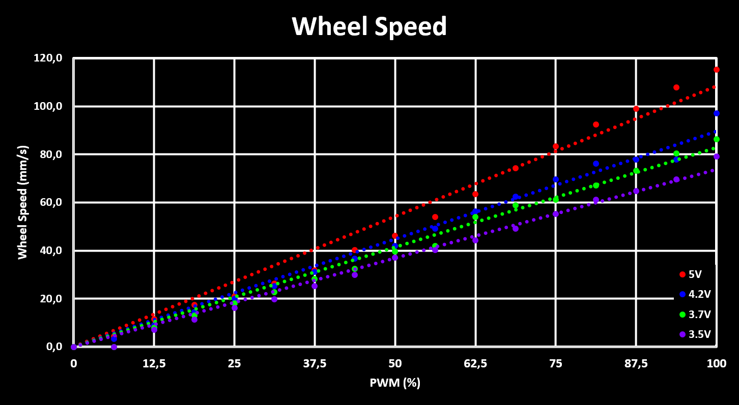
The plots show the RPM, and drive speed, for different supply voltages, simulating a full battery, 4.2V, a almost empty battery, 3.5V, and the nominal battery voltage, 3.7V. Based on this, it can be seen that the expected maximum drive speed of the robot is around 90mm/s with a full battery, and drops to 75mm/s when the battery is getting empty. This means that the maximum drive speed that is reliably achieved is about 70mm/s, which is used as a soft limit in the robot firmware so that the full drive speed range is achieved with any battery voltage.
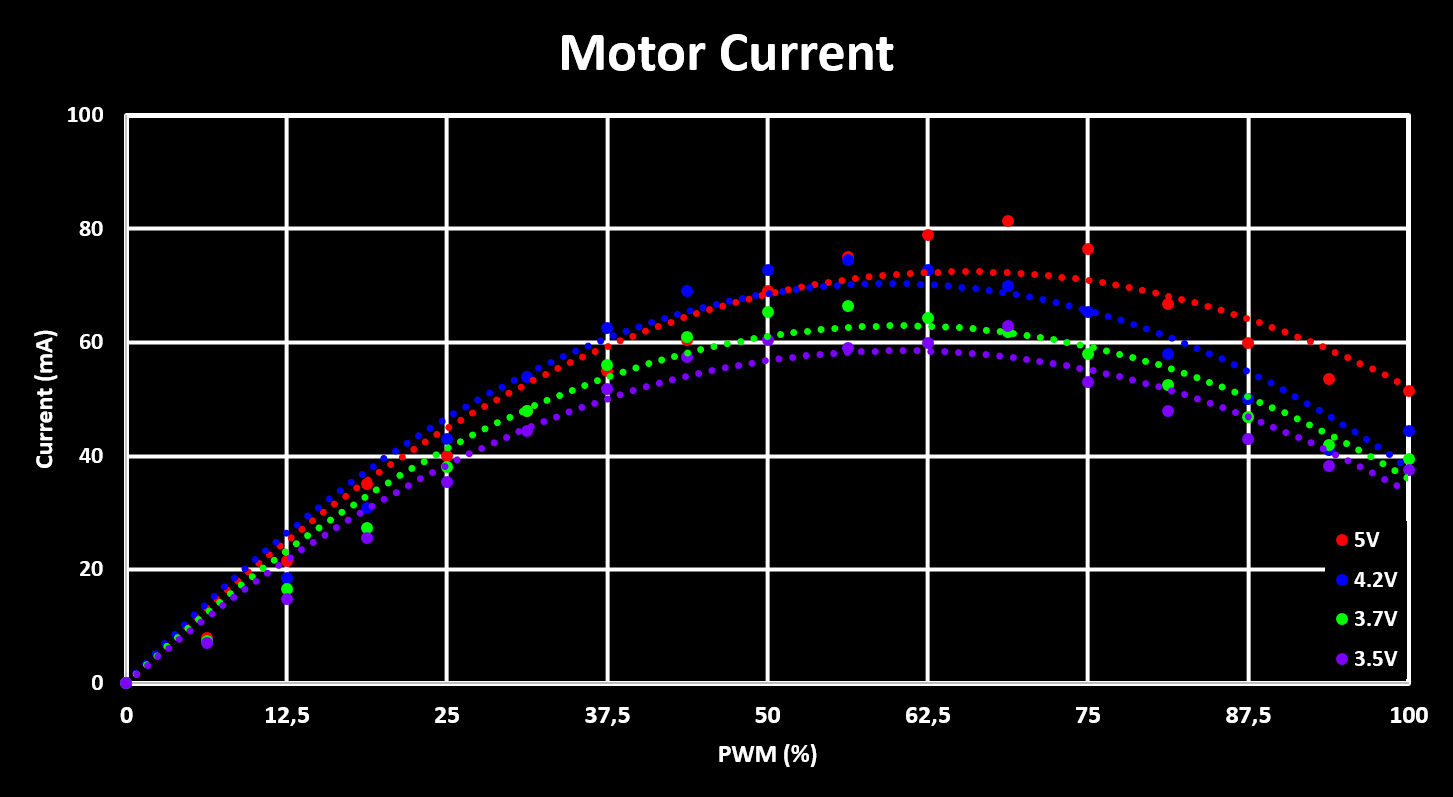
Finally, to complete the characterization of the motor drive, the average current consumption for different PWM duty cycles and supply voltages is measured and plotted, shown in the figure below. Similar to what was observed with the peak current draw, the average current draw also increases with PWM duty cycles, as is expected, but only up to a duty cycle of around 50-60% and then decreases again, which is not expected and has to be analyzed better.
Motor PID Controller
As discussed in the software section, the motor drive controller uses a PID controller with only the P and I terms. The PID controller runs at a fixed 20 Hz refresh rate while the encoder calculates new values at a lower 10 Hz rate, and its output is directly used as the PWM value (0 - 255). The used gain values for the PID loop are 0.5, 16384 in Q15, for the proportional term and 0.6, 19661 in Q15, for the integral term, with the integration time constant, $ Ts = 0.05 $, already integrated. The windup limit is set to the maximum value a 16 bit int can hold, $ 2^{15} - 1 = 32767 $. These values give a fast and stable response without over or under-shoot, confirming that the derivative term is not required. The step response of the controller, for a input step (wheel speed) from 0 mm/s to 70 mm/s and then back to 0 mm/s, is shown in the figure below.
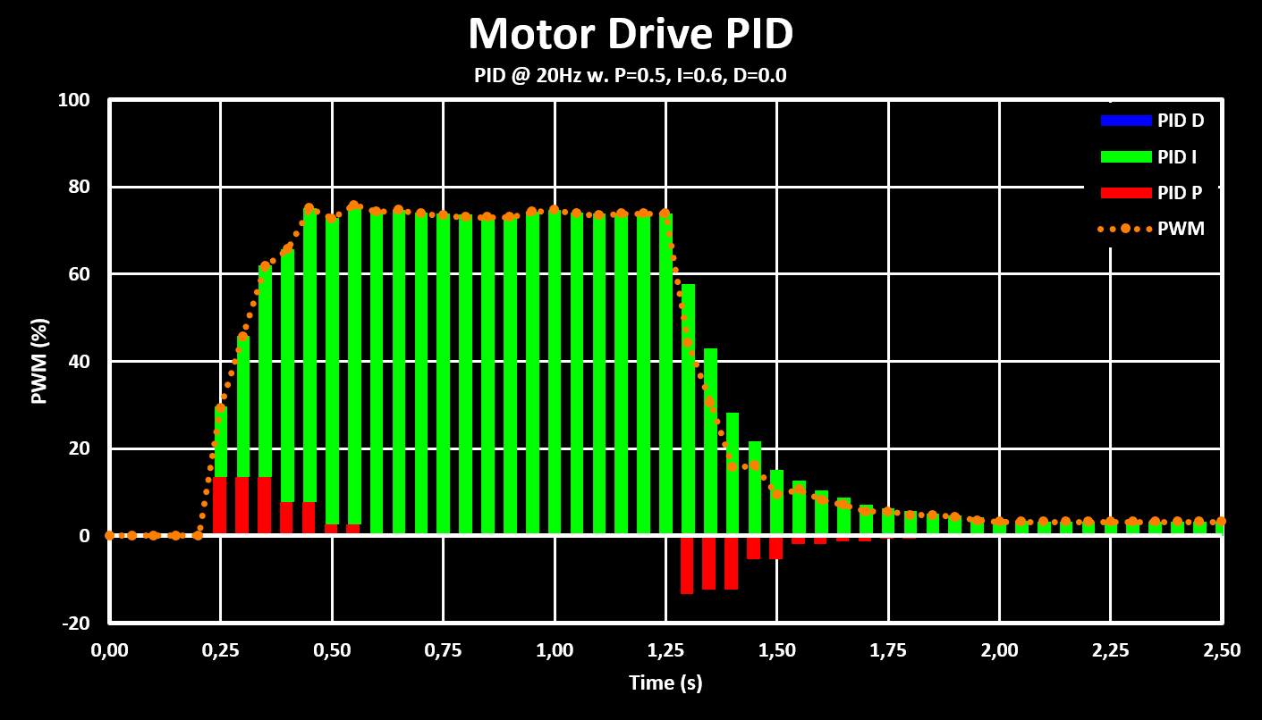
The figure shows that the response time of the controller is around 250 ms for the 0 mm/s to 70 mm/s step but almost double for the 70 mm/s to 0 mm/s step. This is probably due to problems with low PWM values where the motors don’t react correctly or even stop completely. This can also be seen with residual PWM value left at the end, which is due to the motors already being stopped and so there is 0 error.
These settings are then used for a simple drive test, shown in the clip below, where the robot is controlled over bluetooth, from the PC, and the translation speed used is 70 mm/s while the rotation speed is $ \pi \over 4 $ rad/s, or 45 deg/s.
This test validates the rotation and translation speed calculations and that the robot is controlled correctly. It also highlights some problems with the drive train, first it is very loud, some lubrication will be added to help with that as well as testing if increasing the PWM frequency (currently set to 1 kHz) is possible and which will decrease the whining noise. The robot also has some sideways drift, one wheel sometimes spins slightly slower, probably due to higher friction and also because one wheel has a dent in it (from using the hot air gun to close to it…). But all in all the results are satisfactory and serve as a good basis.
IR Reflective Collision Sensor
The Robot Drivetrain holds two collision sensor boards, as seen in the hardware section, one at the front and one at the back. Each of them with three IR reflective collision sensors, a IR LED and a IR phototransistor together in a plastic holder. The IR LED is driven with a resistor, $ R_{LED} $, of 100 Ohm giving a LED drive current of around 20mA ($ V_F $ of 1.25V). The phototransistor is connected to a pull-up resistor, $ R_{DET} $, of 100 kOhm which converts the phototransistor output current into a voltage that is then measured by the MCUs ADC.
The setup used to test the IR reflective collision sensors is shown in the figure below:
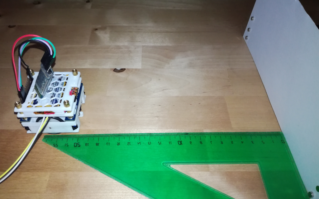
The robot is set at a certain distance from the target and the ADC value of the front facing sensor is registered. The robot is then moved to a different distance and the new ADC value reading is registered, and so on. The distances used are between 1cm and 20cm and two different targets are used, a white and a black paper target. The tests are performed both without any sunlight, window shades closed, and with very little indirect sunlight, window shades open but of a north facing window. This because with any amount of direct or intense indirect sunlight the IR light from the sun is dominant and saturates the phototransistor. In that case only at a very very short distance from the target the actual reflected LED light is sensed, the sensors are actually more sensitive to the shadow from the target then the IR LED light.
Below are the results for the performed tests, both in ADC counts and in calculated phototransistor currents:
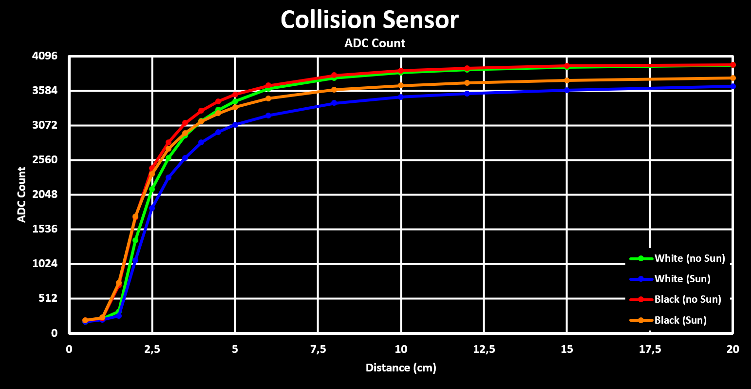
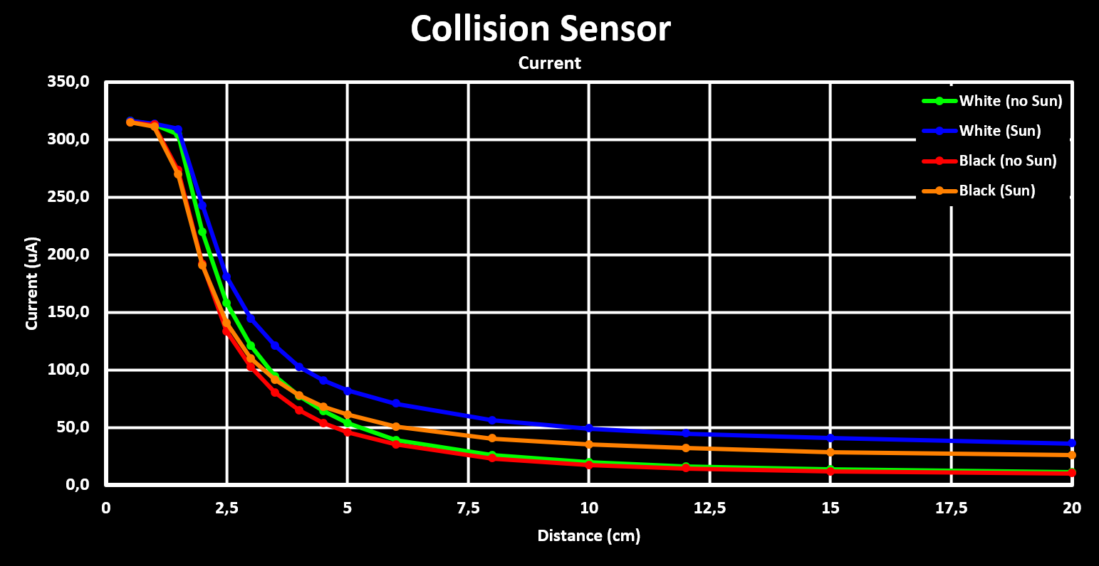
From these results we can see that the IR reflective collision sensors work well for distances below 5cm. In this range the distance can be estimated relatively accurately from the ADC counts, and the difference between a whit and black target are tolerable meaning that the average between both can be used. Above this range the slope (ADC count vs distance) gets to small and therefore shadows or other noise that generate a small error in the ADC reading lead to large errors in the calculated distance to the target.
These results are very good for what the IR reflective collision sensors were designed for, to detect an obstacle at a distance where the robot can avoid it by rotating around the Z (Up) axis, without the need to reverse. This minimum detection distance is 1.5cm, for the worst case with an obstacle at 45° from a sensor, as seen in the hardware section.
LiDAR Board
The Mini Cube Robot LiDAR add-on board is designed around the VL53L5CX Time-of-Flight (ToF) sensor from STMicroelectronics. This ToF sensor features 8x8 separate ranging zones with a 45° by 45° field off view (FoV) giving a angular resolution of 5.625°, and a maximum range of 400 cm, in low light conditions. It also has a fully programable I2C address, allowing easy connection of multiple sensors to a MCU with only one I2C interface, a feature explored here.
VL53L5CX Module:
Schematic: LiDAR_Module_Schematic_V1.pdf
Gerber: LiDAR_Module_Gerber_V1.zip
The LiDAR Board is built up of individual breakout modules for the VL53L5CX ToF sensor, which, besides breaking out its GPIOs, also have all the required decoupling capacitors and pull-up resistors. The module has a 1.25mm pitch header space to which a 7-pin 1.25mm JST connector can be soldered to. The module in shown in the figure below.
Up to 6 of these modules are screwed to a 3D printed holder with M2 screws, keeping them 45° apart, and are then connected to the LiDAR Main Board through a 7-pin 1.25mm JST cable.
LiDAR Main Board:
Schematic: LiDAR_Main_Board_Schematic_V1.pdf
Gerber: LiDAR_Main_Board_Gerber_V1.zip
3D Files (.stl): LIDAR_Holder.stl
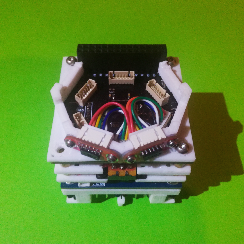
The Main Board is responsible to power, control, acquire and aggregate the range reading from each module. The modules are all connected to the same I2C interface, but with separated interrupt lines, low power (LD) pins and interface reset pins. The LD pin is used to disable all but one module during the set-up phase so that each module can be programmed with a different I2C address. The interrupt pins of each module are connected to independent GPIOs with different IO lines so that each module can trigger an independent GPIO interrupt (EXTI Interrupt). Below is a top down view of the LiDAR Main Board with two modules connected to it:
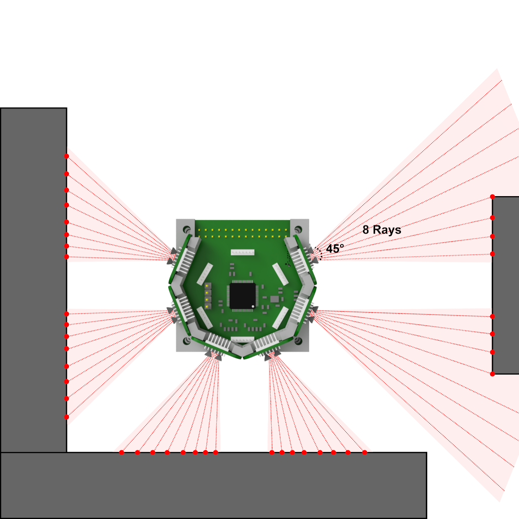
The current LiDAR Board can hold, address and readout up to 6 of these sensors. The MCU collects and aggregates the sensor readings to get a up to a 270° Horizontal FoV range reading with 48 separate ranging zones (rays) giving a angular resolution of 5.625°. Due to the sensors used we not only get this horizontal ranging but also a 45° Vertical FoV with 8 separate ranging zones (rays), resulting in a global FoV of 270°x45° with 48x8 ranging zones. This is shown in the figure below:
The currently used MCU is the STM32F103RCT6 but the module is designed to support higher end MCUs, in case it seems necessary. It is important to use a MCU with at least 128 kBytes of flash as the driver library (ULD) for the VL53L5CX requires almost 100 kBytes of flash memory by itself. Also, to get a high refresh rate of the ranging data, the VL53L5CX supports up to 15 Hz in the 8x8 area configuration, a I2C interface with support for I2C FM+ (1 Mbits/s) is necessary. With the currently used MCU, which only supports up to I2C FM (400 kBits/s), the maximum sampling rate when all 6 modules are acquired is around 5 Hz, with each acquisition being around 1.4 kBytes in size. Also, the power consumption of each module is not to be underestimated, in ranging mode (VCSEL Laser Diode On) they consume about 100 mA each.
Software
The Robot LiDAR Add-On Board firmware is available on Github:
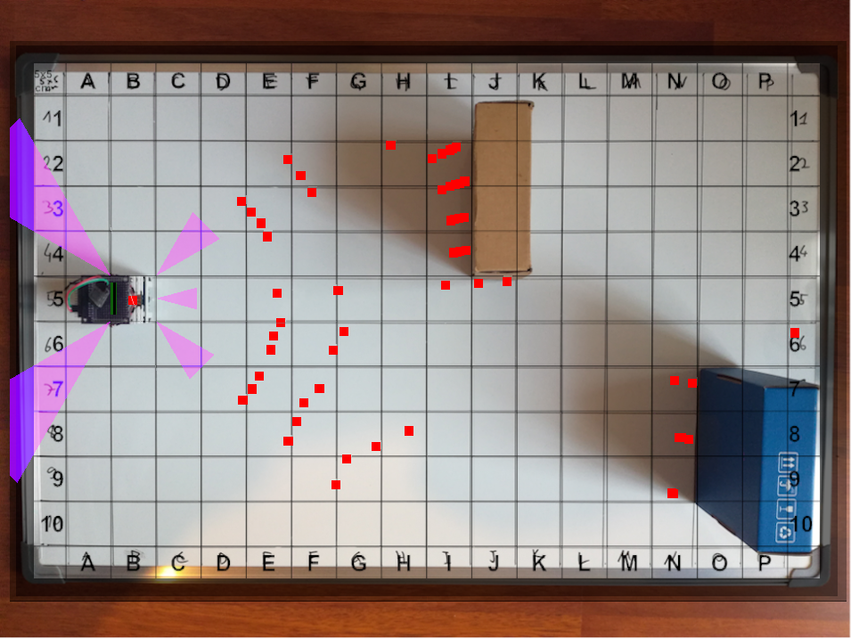
Results
Below is some early results of the LiDAR Module readout sent and rendered in the Robot Hub and then overlayed with a picture of the real scene. To note here that the figure is top down but the ranging information is 3D, meaning that some points are on the surface. Also, the alignment with the picture is not perfect and the FoV is not the best.